Lately I’ve been get more questions about this module. The github repro has some basic information but not the whole story. Here is the background on the module, some insights and some help to make you build one yourself.
The Story
Some time ago I was on the search for a drum trigger module and something to spend my time on. Mutable Instruments share all there products under a open source license. Grids is one of there discontinued modules based on a ATmega328P. This happen to be the same chip that is used by Arduino on there Nano (old one).
These Nano’s aren’t the most expensive and I also keep a few in my drawers. I like working with Arduino’s. Grids PCB’s are avaible on the internet so there wasn’t any need to build a new version. But all those PCB are surface mount parts and non of those uses the Nano. A that chip is a awful thing to solder.
So I thought of build one with through hole components and a Arduino Nano. A bit easier to solder for most people.
The schematics for Grids are public available. But not the files so I started out but just coping it in Kicad. From there on it was PCB design, placing the components and tracing all lines.
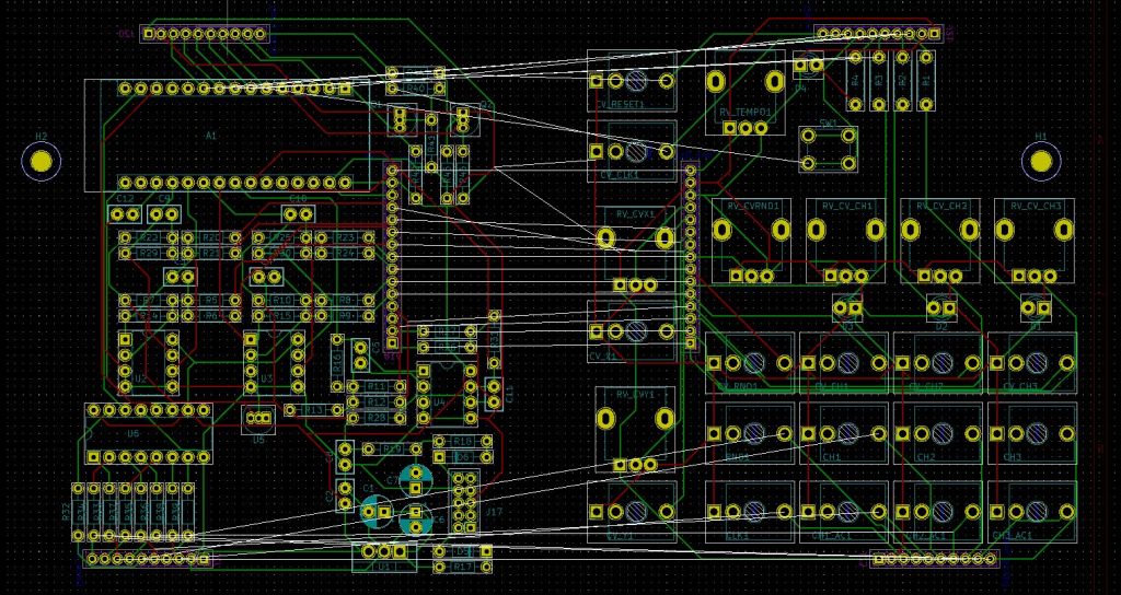
I’m still kinda new to making pcb’s and working with Kicad. I have no education on electronics but that’s not holding me back. But surly it was time to ask some help. I enjoy reading Muffwiggler and know there a lot of knowledge there for the Diy community.
https://www.muffwiggler.com/forum/viewtopic.php?f=17&t=223908
Help was there and before that I didn’t know about decoupling caps and how to read these from a schematic.
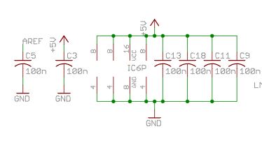
Why don’t the draw these where the sit but just below on the schematics ??
My designing of the board may seem a bit weird at first (and second..). I wanted to make two board that will fit on top of each other. Otherwise it would be a realy big module. I designed it as one board where I could delete half of the board to make the Gerber files needed for the PCB manufacturer.
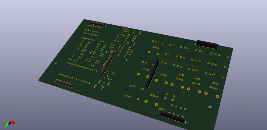
In the end I had to do it three times. First time the potentiometer where wrong way round, made a few footprint mistakes and still on the last board there are a few issues. But I got these from the manufacturer
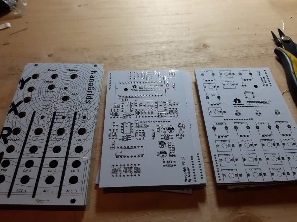
The known issues
- The boards had a few production runs (3) and the last issues where workable. A wire had to be soldered between the tempo pot and ground. Lucky ground was very nearby.
I think I got this sorted on the github repro upload but didn’t order the board myself. Three times was enough. So I hope some will test this and report back to me. Else I still have so minor work to do and a new Github upload is needed. - The led lights might be a little to bright with the current BOM, It’s a matter of opinion. But if you want to change them. (R25, R26,R27, R28)
- Power header and diodes are tight fit. Might wanna install the diodes last.
- A fellow “Wiggler” reports: The resistor R31 before the LM4040-5V is a 100k in Quinie’s design but a 10k in Mutable Instruments. (I have to double check but trust Mutable Instruments, I could have made a mistake here )
- panel hole for button might be a bit to big or small (depends if you use buttoncaps)
What should I’ve done differently
Well a lot of things maybe, but the files are out there and I can still update the current version. But one thing I would still like to do is matching it with a normal Grids panel layout.
Building It yourself
If you don’t want to order a multiple board (most go from 5 pcb and above) you can always send me a email. I might have few in stock as people keep asking me about it.
You can check my Github repro and order some boards and start from there (BOM below). If you have any question please drop me a email, wiggler message or github issue.
Some Pictures from builders
by migueldetrool
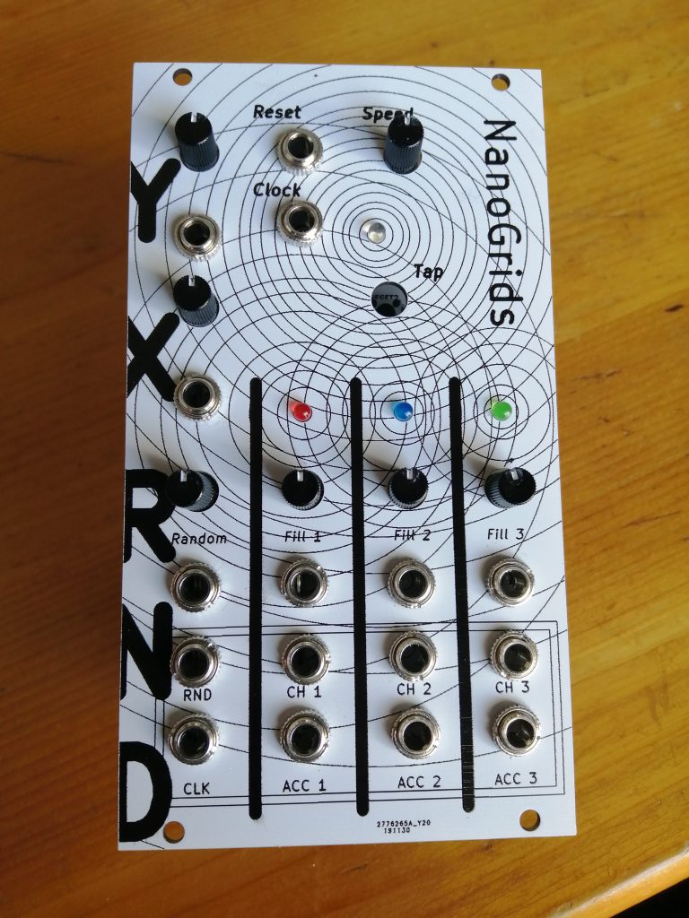
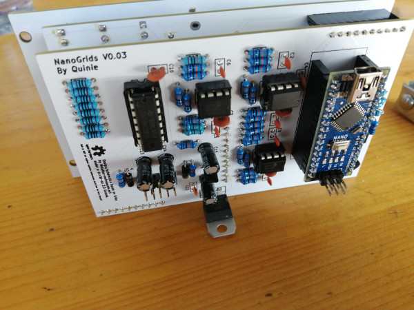
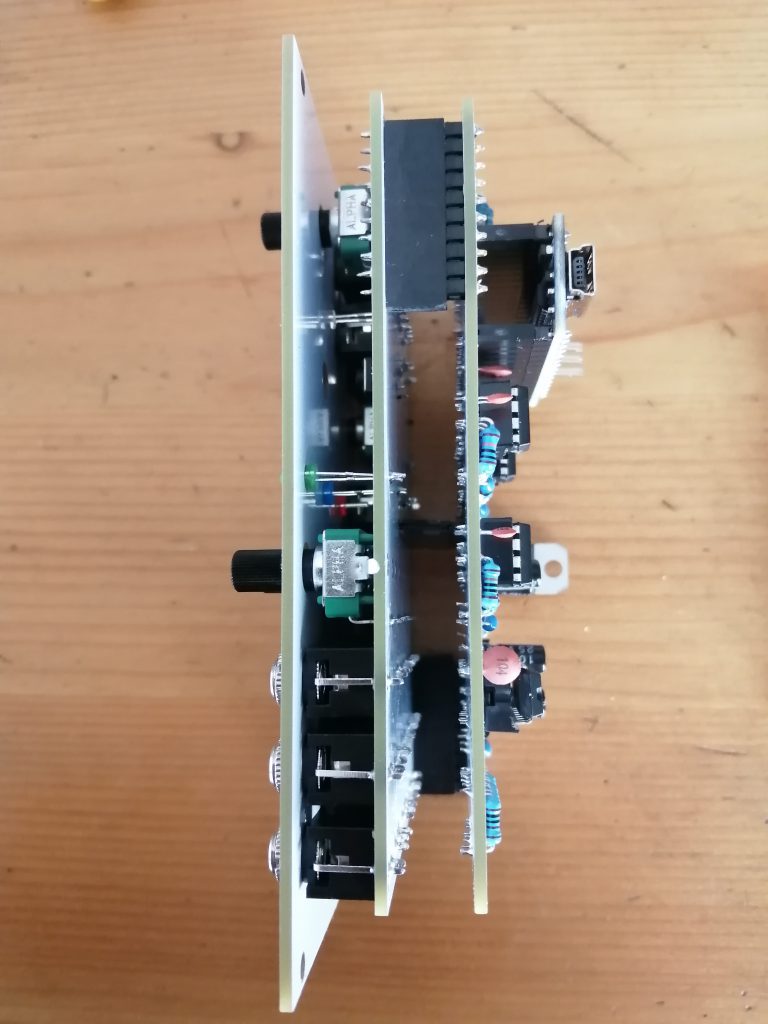
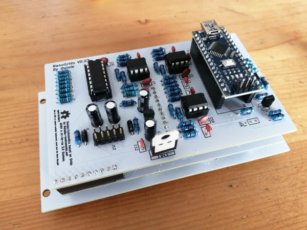
Credits
Thanks to all wiggler that helped on creating this. a special thanks to migueldetrool for doing a lot of testing a providing me with some issues reports.
Bill of Materials
| Arduino_Nano_v3 | A1 |
| 10nf | C1,C2,C5,C6,C8,C9,C12 |
| 10uf | C14,C13 |
| 0.47uf | C15,C11 |
| 100nf | C4,C3,C7,C10,C16 |
| CH1 | CH1 |
| CH1_ACC | CH1_AC1 |
| CV_CH1 | CH1_FILL1 |
| CH2 | CH2 |
| CH2_ACC | CH2_AC1 |
| CV_CH2 | CH2_FILL1 |
| CH3 | CH3 |
| CH3_ACC | CH3_AC1 |
| CV_CH3 | CH3_FILL1 |
| ClockOutput | CLK1 |
| CV_CLOCK | CLOCK1 |
| CH1 | D1 |
| CH2 | D2 |
| CH3 | D3 |
| CLK | D4 |
| 1n4148 | D6,D5 |
| Fiducial | FID1 |
| Fiducial | FID2 |
| MountingHole | H1,H2 |
| Conn_01x12 | J10 |
| Conn_01x12 | J11 |
| Conn_02x05_Odd_Even | J12 |
| Conn_01x10 | J14,J15 |
| Conn_01x03 | J16 |
| Conn_01x10 | J7,J13 |
| 10k | P_TEMPO1,P_CH2,P_CH1,P_X1,P_CH3,P_RND1,P_Y1 |
| 2N3904 | Q2,Q1 |
| 100k | R1,R2,R3,R7,R4,R5,R6,R8,R9,R10,R11,R15,R12,R13,R14,R16,R17,R18,R19,R23,R20,R21,R22,R24,R43,R44,R45,R42,R41,R40,R31 |
| 100r | R25,R28,R27,R26 |
| 10r | R30,R29 |
| 1k | R39,R38,R37,R36,R35,R34,R33,R32 |
| CV_RESET | RESET1 |
| SW_Push | RESET2 |
| RandomGate | RND1 |
| CV_RND | RND2 |
| MCP6002_1 | U1,U2,U3 |
| L7805 | U4 |
| LM4040LP-5 | U5 |
| 74HC595 | U6 |
| CV_X | X1 |
| CV_Y | Y1 |
Hello Quinie.
I am currently also working on an Arduino version of the MI Grids, and found your homepage.
I have problems in turning the open source code into an Arduino code to be uploaded, as I am not much skilled in C and Arduino programming.
I saw you have a HEX code which can be uploaded.
I thought I use that one.
But I also saw that your module layout differs from the original Grids.
So I am not sure if I can just use your HEX file.
You have 2 additional jacks, CLK and RND on the bottom left.
I basically just used the MI Grids schematics and the ATMEGA328 to Arduino Nano pin conversion.
Would there be any issue if I use your HEX code?
Or can you give me some advice how to convert the original code into something for the Arduino IDE?
Thanks,
Daniel
You can use the HEX file. I did not change any code. The clock and the random are on JP1 in the schematics.
https://forum.mutable-instruments.net/t/grids-clock-out/657
My schematics and pcb’s files are on GitHub to use as the license from Mutable Instruments instructs. Looking forward to see your project. Any changes compared to what I have done?
You could use the mutable instruments development virtual machine to build the code. I used a raspberry to make the code into a HEX. To convert it to the Arduino IDE would mean just to add an ino file. But that’s cause the IDE can work with C code also. I don’t know if I say this correctly but Arduino is a simpler form of writing C++. If you want to you could just write C or C++ and upload it with the IDE.
Something like analogRead() is just a wrapper that contains code to do the reading. You could read the Atmel a bit faster when not using the wrapper and bypass some check straight in C code.
hope this helps you out a bit. If any question do come up please comment again, here to help out.
Thanks a lot for your advice.
I realized that the 2 extra jacks in your design (random gate and clock output) are also available in the original MI design, but they are only available via connectors at the backside, not in the front panel.
My design and front panel is the same as the original one.
That would be the only difference to your design, I guess.
I was able to upload your hex file to my Arduino.
Thank you very much for that!
I am currently waiting for my PCBs to arrive, so I can build it.
I do not have MCP6004 op amps available, so I will try it with other ones.
Hope, it works out well.
Let me know if it works out. I always wanted to update mine to fit a original panel. So glad someone is doing that. Also the use of a different opamp would be nice to know if that works. I think it will believe the mcp6004 isn’t rail to rail so just one like it should work (did the same on a Hagiwo design with a mcp6002).
Please keep me updated on your progress and if you have a GitHub can you send/post the link?
I finished the built, but I am struggling with an issue, when testing the module.
The clock looks fine.
I can adjust the speed, tap my own speed, and also switch into the options mode by pressing down the tap longer.
But I do not get any pulse out of the Arduino at the three channel pins.
Also the LED pins for the channels do not send any signal.
I just used your HEX file and uploaded it to Arduino.
Wondering if I configured the pins incorrectly, since at least the clocking part works fine.
I use the following pins on the Arduino Nano, following the original MI design:
CH1 CV – A3
CH2 CV – A4
CH3 CV – A5
CH1 LED – D7
CH2 LED – D6
CH3 LED – D5
Any idea, what might be wrong?
Sorry, my last reply was stupid.
The CV pins are of course for the CV control of the channels, not the triggers.
Anyway, I think the LEDs should at least light up, like the clock LED.
So still not clear to me, what is wrong.
Concerning the Github link.
I did not yet upload anything, since I first want to make it work.
If I can make it work…
I did a quick look at my schematics and believe you have the correct Arduino pins connected.
You could always test it with your own sketch just to test if the pins go high and low for the leds and if the CV arrives at the Arduino.
Ok, I dug a bit deeper.
The issue is not with the Arduino, but the Op Amps.
I tried it with TL074 and TL072.
There is no correct signal sent to the Arduino CV inputs.
Since the clock signal does not make use of an Op Amp, it works fine.
By coincidence I found that the triggers are working, when the Op Amps are not on the board.
Of course then I cannot control the trigger frequencies anymore.
But at least the module id firing.
I decided to order a few MCP6004 and MCP6002 online.
I will try again, when they arrive.
Hope that will then work out better.
Will let you know.
TL07X are rail to rail opamp’s (-12 and +12v) MCP600X are not rail to rail (max 6v).
https://electronics.stackexchange.com/questions/224159/what-does-rail-to-rail-output-opamp-mean
I finally completed the module. It now works perfectly. Thanks a lot for your help. I uploaded a YouTube video, if you are curious about the result: https://youtu.be/aDjtfZ6hMfQ
https://www.quinie.nl/nanogris-big-bom-mistake-update-for-better-range-on-pots/