
I build a few modules that I use a lot in my rack. These modules aren’t the most fancy ones. There used as routing signal and duplicating signals.
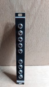
The most basic one is the non-buffered multiple. Mostly used for routing gates and triggers. I does not have to be powered and basically just connect audio-jacks with each other. Then there is the buffered version for precise buffering and I made a dual switch for gates and triggers.
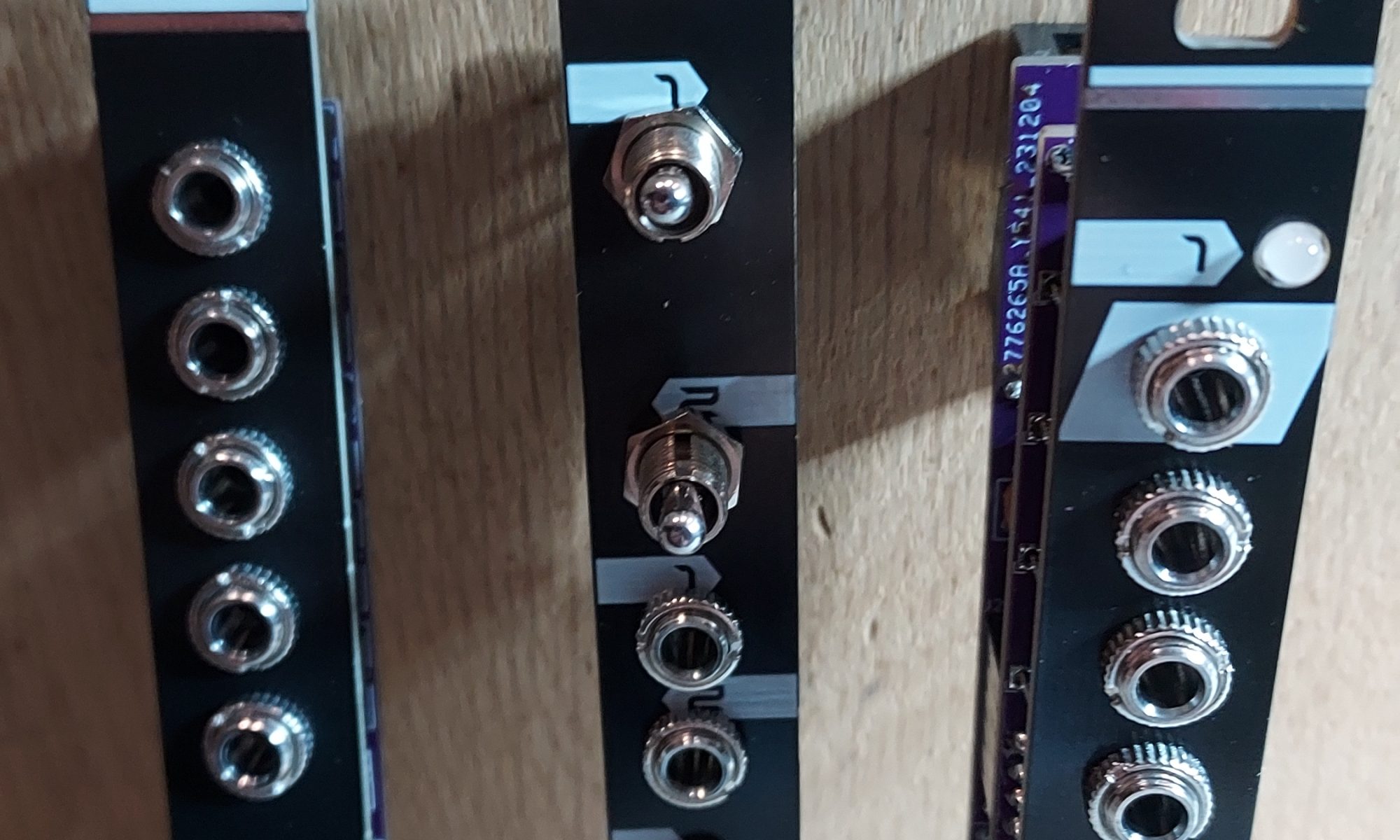
The Non buffered Multiple
This is quite a simple build. Just place the jacks on the PCB. Put the panel on, flip and solder the jacks in place. I tend to lay the panel on two holders (books or something) so the jacks sit inside the panel and are being hold down by gravity, then solder the jacks.
A other trick is just to solder the top and bottom jack first. Then place the other jacks and use the panel to hold them in place. Use the top and bottom ring mounted on the two soldered jacks to keep the panel in place.
This module is passive. This means it needs no power so there is no power connector on the PCB.
The Switch
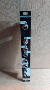
Just like the Non Buffered Multiple this is a passive module. It can be routed in two ways. One audio-jack is connected to a switch. The switch can be in the middle position and the signal is unconnected. The switch can be at the top or bottom position and connect with one of two jacks.
So you can connect two sources and route them to one output, or mute the output. You can run one source into two outputs all controlled by a switch.
The only downside is it’s not really suited for audio signals. I use them to control triggers. Muting the trigger for a bass drum or route it to a different bass drum.
The PCB and panel have two switches so it’s a double.
The Buffered Multiple
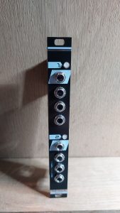
This module is quit handy for taking a 1/v octave signal and routing it at a precise voltage to multiple VCO, precision adders and other modules that depend on a precise signal.
The schematic and function for this comes from using an opamp chip (tl074). Input of the opamps are connected and draw as Non-inverting Operational Amplifier Voltage Follower. One output is used to drive a dual led to show input value a bit visual.
The remaining three outputs are connected to the output jacks. The are two of these chips on the PCB so you will get a dual buffered multiple with three output each.
The Files
The files for these modules can be downloaded from GitHub (https://github.com/Quinienl/Basic-Modules) to make your own boards. Or you can other them in the shop section. PCB and panels and kit’s