I got some good feedback and wanted to share the answers for other users. Here is a post about some questions regarding the modules on this site. Some building tips and updates.
Nanogris
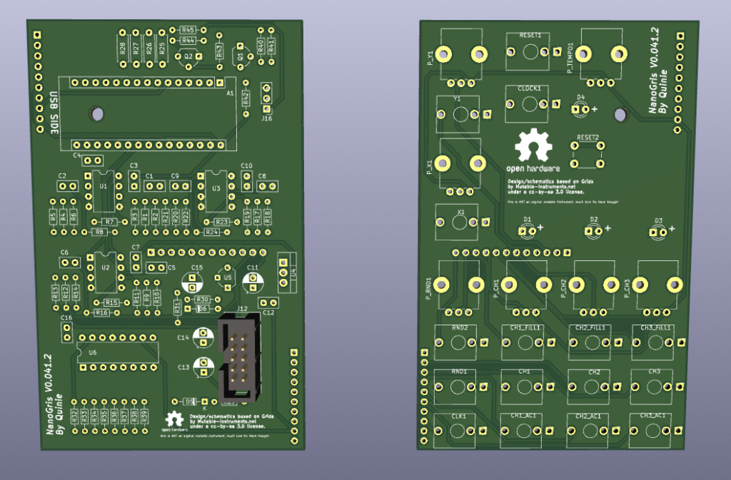
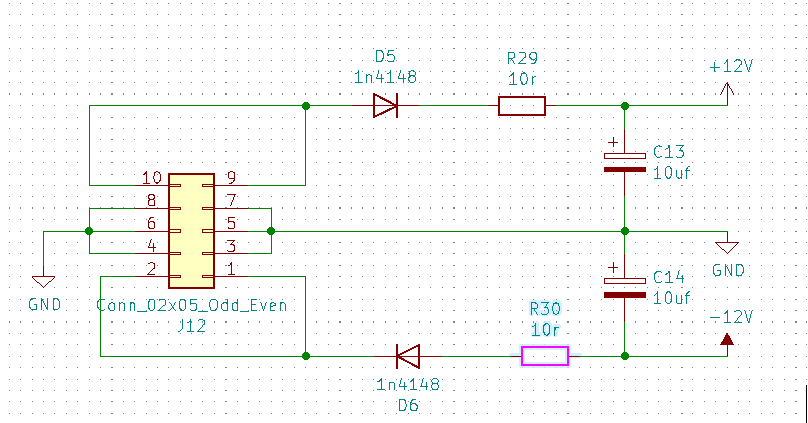
The powerheader schematic was flipped. The module it self didn’t display a red line or boxed header. When using a unboxed header this should not be a problem just follow the lines to the diodes. A lot of users where able to figure it out, but why should you have to figure it out when the solutions is/was quite simple.
Make a correct schematic and use a boxed header footprint on the pcb.
I updated the Kicad files for a boxed header and the correct schematic is uploaded to GitHub. I added a new version number 0.41.2. This was a bugfix, no real version upgrade still 0.41 but easier to make the power headers correctly.
Hagiwo Quantizer
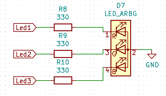
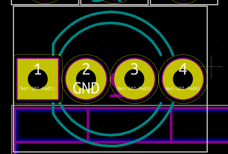
What about that led? Is it a common anode or common cathode?
To be honest I just used the leds in my drawer and made the pcb’s work with them. But looking at the schematic and pcb it’s a common cathode.
But what about the programming header of the Arduino. (Sorry Chris you had to find out the hard way and blew a Arduino, and thank you for the incorrect version picture)
Below is a picture that is incorrect, I made the picture Red to inform you NOT to place the header like shown. The Arduino normally use a L shaped programing header. Please use a straight one cause using a L shape it can make contact with the rails of the rack.
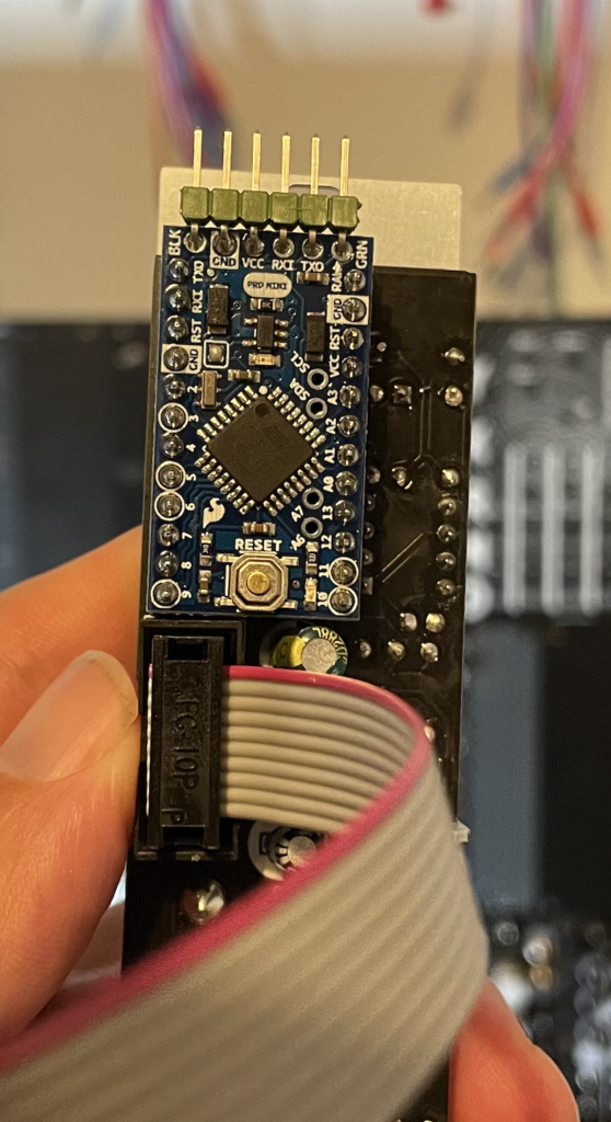
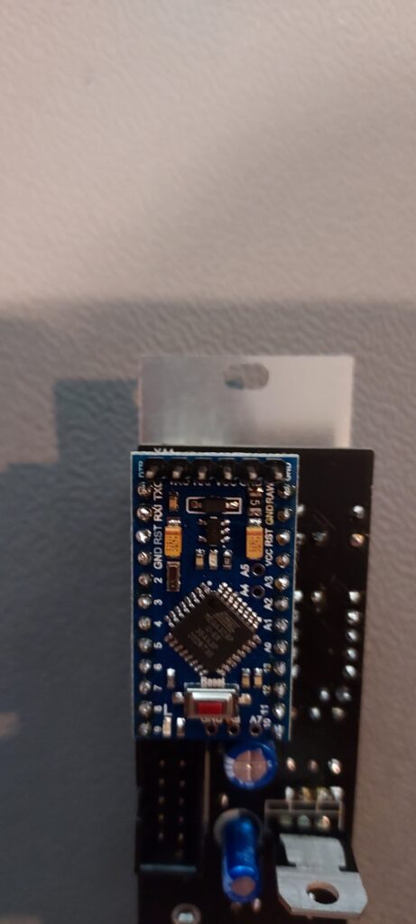
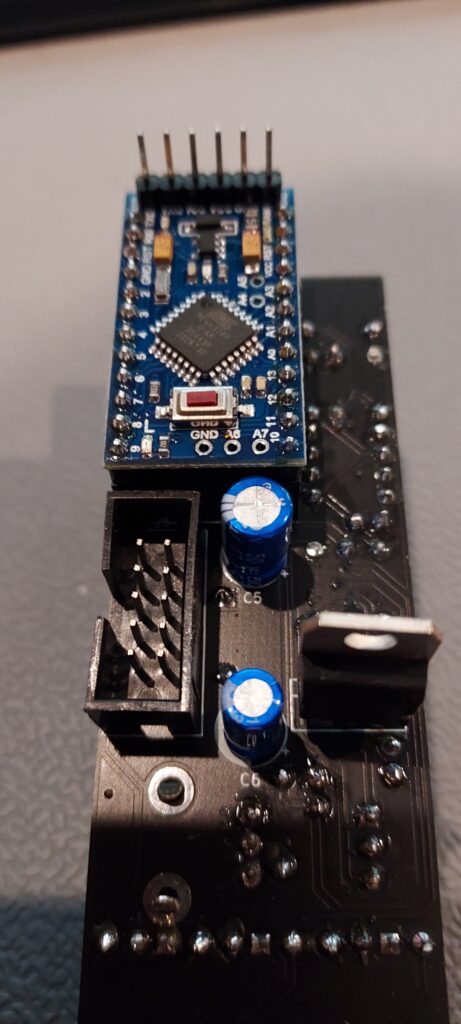
Kicad footprint for the Arduino Mini is missing and in the schematic it’s called version 2 isn’t it a version 3?
Yes it is a version 3. Kicad has a few footprints for Arduino’s but none for the Mini. So I downloaded a footprint and used it. It seems to be a old one and for the version 2. I only used some pins that where the same so when making the module this worked for me. But it wasn’t handy for others, cause it leads to many questions.
For the new works on Littleben (uses a Arduino Mini too) I found a new footprints so hopefully will be updating the GitHub for the Littleben and Quantizer soon with this new one.
I hope this answers some build questions. I am always open for feedback and update request by comments and email. I still have a few things on the todolist but hopefully this will help you out during the build of these modules.
Thank you Chris, Miguel, and others for giving me the feedback and contacting me with your questions.
Quantizer uses common cathode LEDas you wrote, but your diagram shows a common anode LED.
Hi Robert,
Thank you for replying. I had to double check but believe text and diagram are correct. De resistors are connected to the led. The all on the positive side (anode). The arrow on the led diagram shows the direction of energie flow going to ground, negative side (cathode). The 3 resistors are connected to one ground pin (common).
Hi Robert,
Thank you for replying.
I had to double check but I believe text and diagram are correct. De three resistors are connected to the led. These resistors are on the positive side (anode). The arrow on the led diagram shows the direction of energie/current flow going to ground/negative side (cathode), one ground pin (common).
https://makeabilitylab.github.io/physcomp/assets/images/RgbLEDS_CommonAnodeVsCommonCathode.png
more info on
https://makeabilitylab.github.io/physcomp/arduino/rgb-led.html