
The Quantizer made by Hagiwo is a Arduino based quantizer. Hagiwo published all files and schematics. The code is readable and not packed into a hex files. I have put my own twist on the design by replacing the DAC.
The original post and design by Hagiwo can be found here:
https://note.com/solder_state/n/nde97a0516f03
So lets take a look on how it’s build and how it works.
Before I start explaining things, I have no education on electronics. I hope to have learn a few thing along the way. I will try too explain as much as possible but feel free to use the comment section to correct me, ask questions or give feedback.
CV input
First we need some input voltages to quantise. The voltage arrive at the Arduino at pin A7. These voltages go thru a small circuit of resistors and diodes. As far a I know these resistors are here to protect the Arduino from too much current coming in.
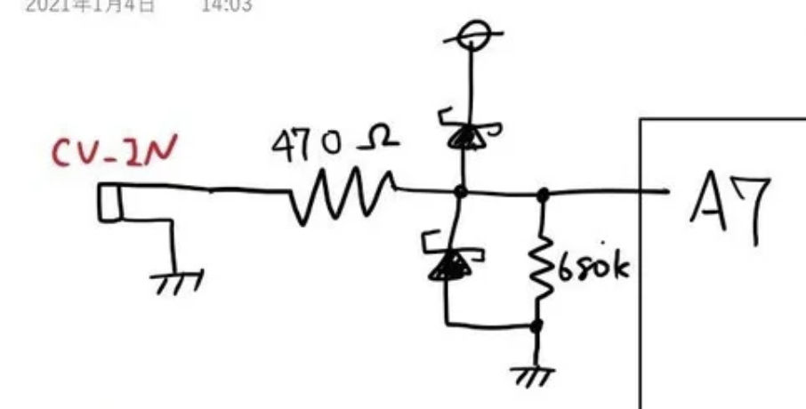
The diodes are so called “clapping diodes”. I can write a paragraph about them but there are lot’s of resources that explain it better then I can do. But basically these protect for over voltages. In Hagiwo’s setup these will only allow voltages between 0 and 5 volts to pass on. Below or above 0 to 5 volts the diodes will open and release the current.
You need this kind of setup to protect the Arduino agains voltages. The pin only allow for 0 to 5 volts. Where eurorack normally works with -12 to 12 volts we don’t want these voltages to arrive at the Arduino pins.
This also means if we put -12 to 12 volt LFO into the CV input it will only pass thru 0 tot 5 volts to the Arduino -12 to 0 volts is dropped before arriving and 5 to 12 volts is out of bounds also. So only a small portion of the LFO will arrive at the Arduino to be quantised.
Arduino Code
When the voltages arrive at the Arduino we puts this in a variable “float CV_IN = 512;”. When the code is run in the loop part we see the first actions with this variable.
old_CV_IN = CV_IN;
The current value in the variable CV_IN is copied to an other variable “old_CV_IN”. This way the code knows the old value in memory and can read the pin to overwrite the CV_IN variable to the new value.
CV_IN = analogRead(7);
Note: on the Quantizer I moved some pin connections. The CV is connected to pin A0 and read by variable name cvPin. CV_IN = analogRead(cvPin);
The pin is read. Note here is that Arduino read pin value in a range from 0-1024. As we know from the CV Input part the voltages will be between 0 and 5 volts. These will translate to 0 and 1024 max. This has to do with 10 Bit resolution of the Arduino pins.
https://www.arduino.cc/reference/en/language/functions/analog-io/analogread/
When 0 volts arrive at the pin, it will translate to a value 0. But when 5 volts arrive it will translate to 1024. There are only 1024 values to make any measurement between 0 and 5 volts. I would be nice to have around 5000 values. But we have to do with 1024 so there will be some threshold here small difference in voltages will be given the same value.
After the reading of the pin, we kinda know what voltage arrives at the Arduino, is it 0 or 1024 or somewhere in between.
A difficult part
In code the scales are set as a group of values. The values are indexed mean we can call the variable with all the values and give it an index number. It will give back the value stored with the index number.
const static word DAC_LSB_maj[61] PROGMEM = { 0, 137, 205, 341, 478, 546, 683, 819, 956, 1024, 1161, 1297, 1365, 1502, 1638, 1775, 1843, 1980, 2116, 2185, 2321, 2458, 2594, 2662, 2799, 2935, 3004, 3140, 3277, 3413, 3482, 3618, 3755, 3823, 3959, 4095 };
const static word CVIN_th_maj[62] PROGMEM = { 0, 15, 44, 73, 102, 131, 160, 189, 218, 247, 276, 305, 334, 363, 392, 421, 450, 479, 508, 537, 566, 595, 624, 653, 682, 711, 740, 769, 798, 827, 856, 885, 914, 943, 972, 1001, 1024 };
Lets make it a bit smaller to explain
DAC_LSB_maj[2] PROGMEM = { 0, 137};
Here we have a variable DAC_LSB_maj. The names is followed by the amount of values we want to store in it. In the small example the number 2. Then the values for this variable group are store {0, 137}.
When the code finds AC_LSB_maj[1] it will hold the value 137 (they count from 0). AC_LSB_maj[0] will return 0
The code has two variable groups, one for the CV_IN values CVIN_th_maj[62] and one for the values needed for the DAC (more on that later). There is a part of code that takes the CV_IN value
if ( CV_IN >= (pgm_read_word(&(CVIN_th_maj[i]))) && CV_IN < (pgm_read_word(&(CVIN_th_maj[i + 1])))) { CV_INh = i; DAC(pgm_read_word(&(DAC_LSB_maj[CV_INh])));
If you look too long at it, it might dassle you. But let’s deconstruct this part.
If CV_IN is bigger or equal too CVIN_th_maj[index] and CV_IN is smaller then CVIN_th_maj[index +1] Then do DAC.
So basically it try to find within the CVIN_th_maj group where the CV_IN values match most. Let take the first five values { 0, 15, 44, 73, 102} and let say we have a voltages just above 0 volts coming in at the Arduino pin and between 0-1023 it’s reads 56.
56 is bigger then 44 and smaller then 73. So the code selects 44. This is the third value and counting from zero we now know the index (2).
The code will look in an other group for a value to send to the Dac. It uses the found index.
DAC_LSB_maj[61] PROGMEM = { 0, 137, 205, 341, 478, 546, 6…….}
We know the index so the value from DAC_LSB_maj[2] will be 205 This value will be send to the DAC.
The DAC
The DAC has been replaced for a MCP4821 12 bit. I did this cause this dac is cheap and possible to solder without SMD (small parts). I added a few line to Hagiwo code to include a library to use the DAC. Adjust his output to use the DAC.
Wire.beginTransmission(0x60); Wire.write((old_CV_OUT + (CV_OUT – old_CV_OUT) * j / slide_time >> 8) & 0x0F); Wire.write(old_CV_OUT + (CV_OUT – old_CV_OUT) * j / slide_time); Wire.endTransmission();
became
MCP.analogWrite(old_CV_OUT + (CV_OUT – old_CV_OUT) * j / slide_time, 0);
And while writing this I might have to double check the & 0x0F if I'm not missing values.
I did not change any values in the groups that are used to match the input voltage to a Dac value. The DAC takes values between 0 and 4096.
Conclusion
The Quantizer works with 0-5 volts CV in. There are some translations to internal values 0-1023. This translation will not be very precise. And will be transform into values for a Dac that has more bits then the incoming values.
I can work nicely as a Quantizer where in principle detuned notes (voltage offset) are matched to a note (precise voltage). That exactly what the code does. Find the voltage match it to a note value and output that note.