
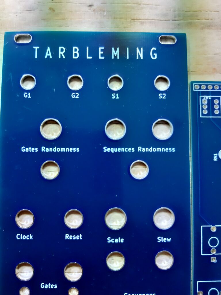
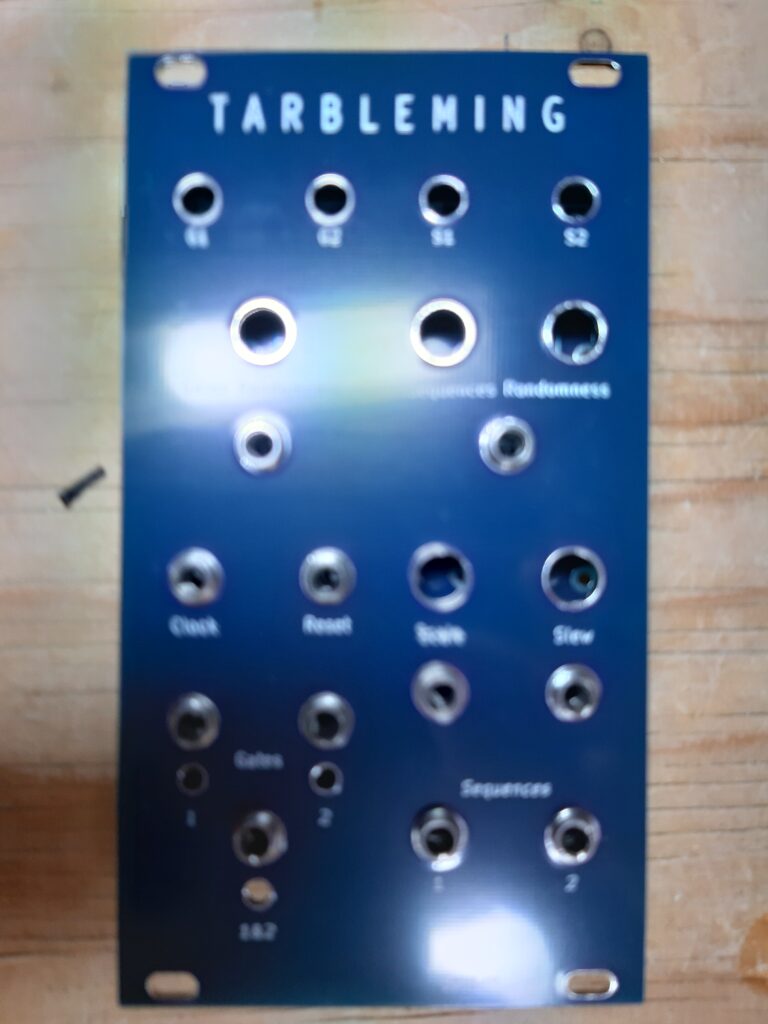
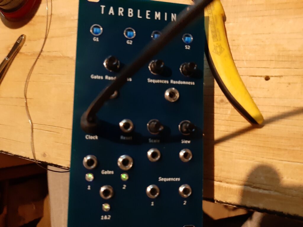
Last week I found a package in my mailbox. I didn’t expect a package so there was some surprise. I contained two pcb’s and a panel, on the panel there was a big text “Tarbleming”. Haven’t seen a module called Tarbleming before, don’t know what it is or what is does but it looks Good!.
I soon found out it was send to me by Miguelddetool. He made the PCB’s and panels. He told me this wasn’t a finished product. This product is not available at this time. It still is a prototype but I’m very happy to received one. Let’s build it.
There is nearly no info to be found about this module, I received a message from Migueldetool containing a BOM, some code and basic instructions. I read the BOM and started building it. Forgot about the instructions.
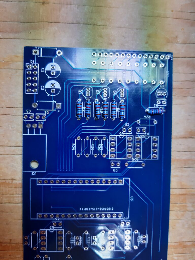
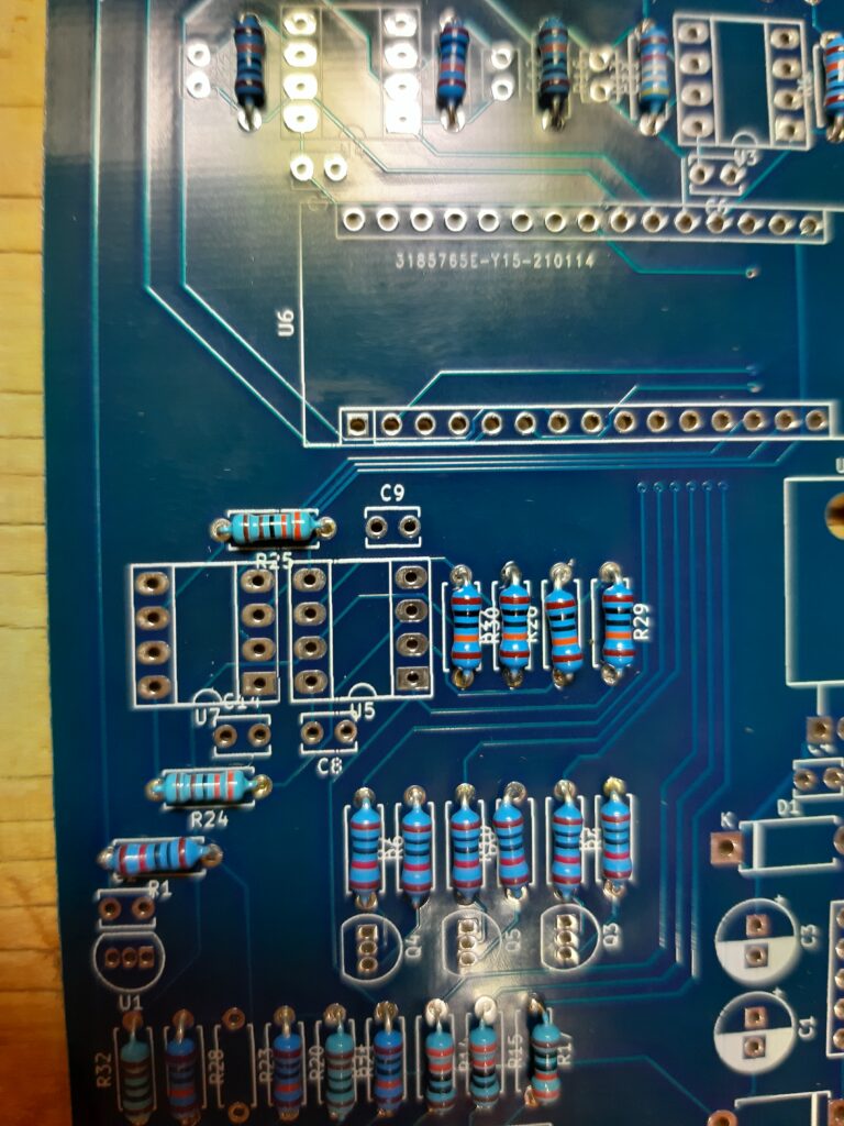
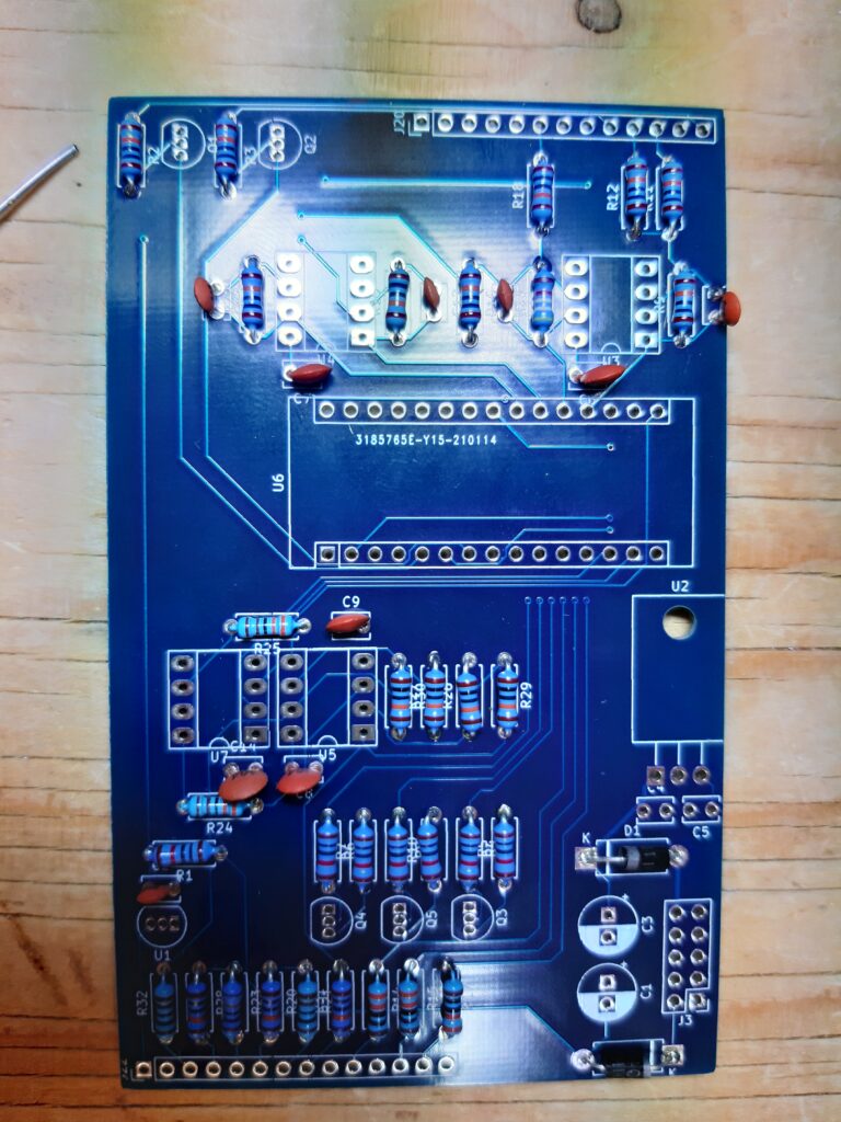
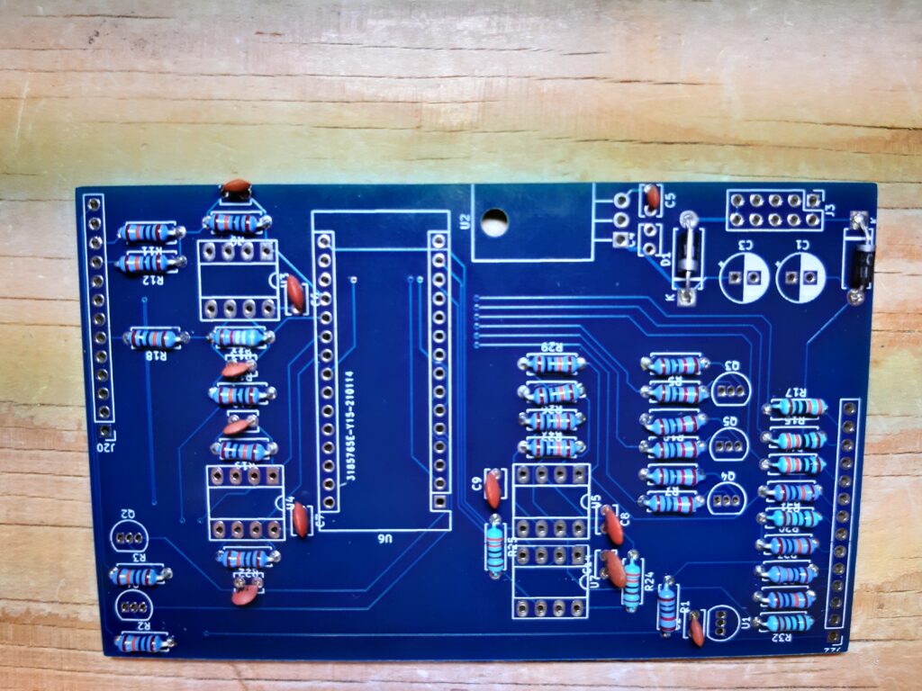
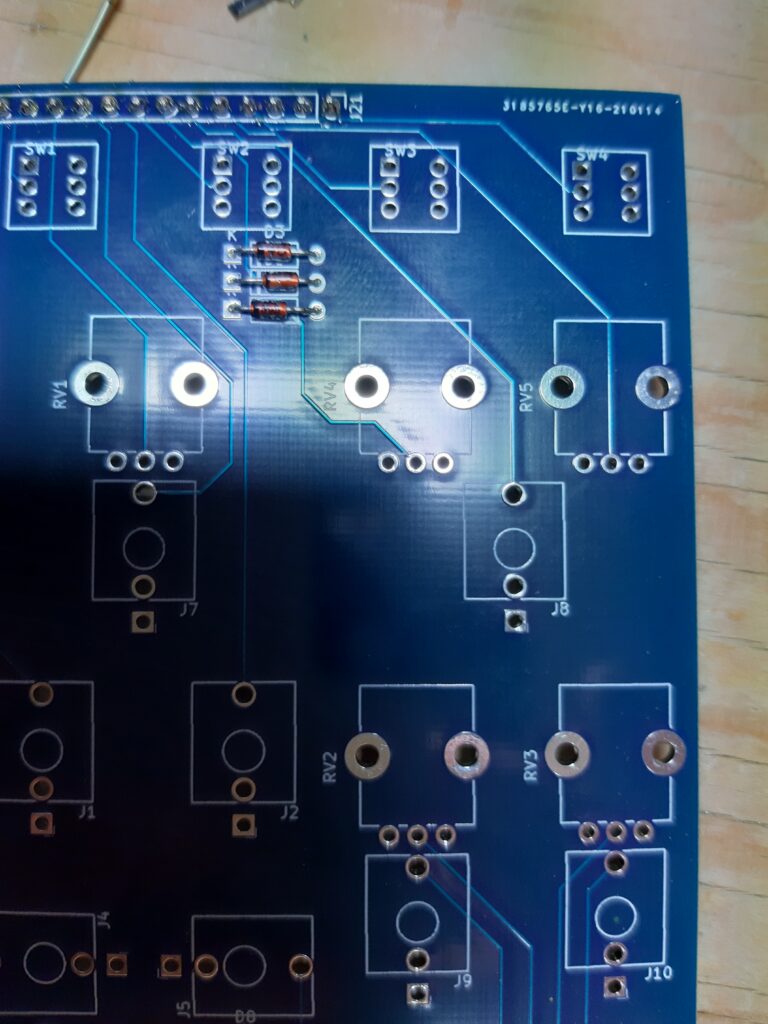
I could see this was a prototype board. The silkscreen was a bit off and I have to guess two or three positions. I do this myself sometimes when I’m a bit lazy on prototype boards. Parts are going to be placed differently or left off on the finished product so there isn’t really need to place the silkscreen nice and tidy.
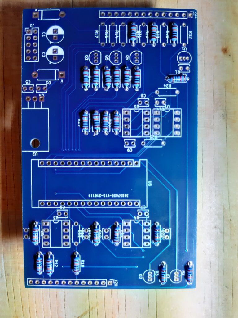
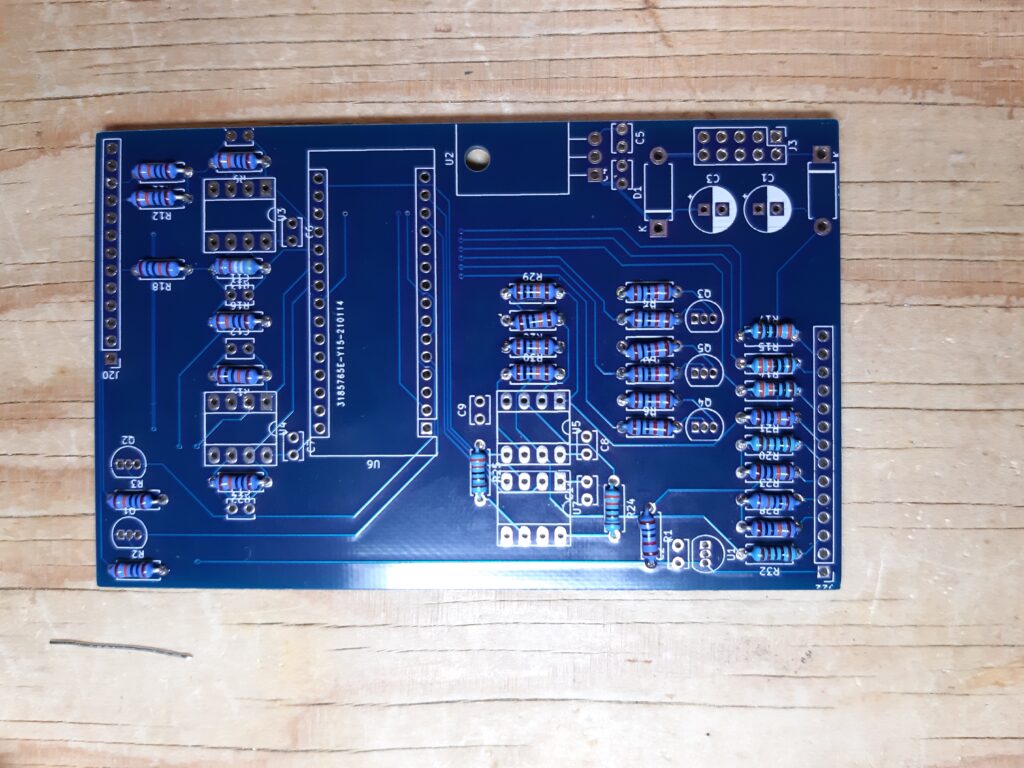
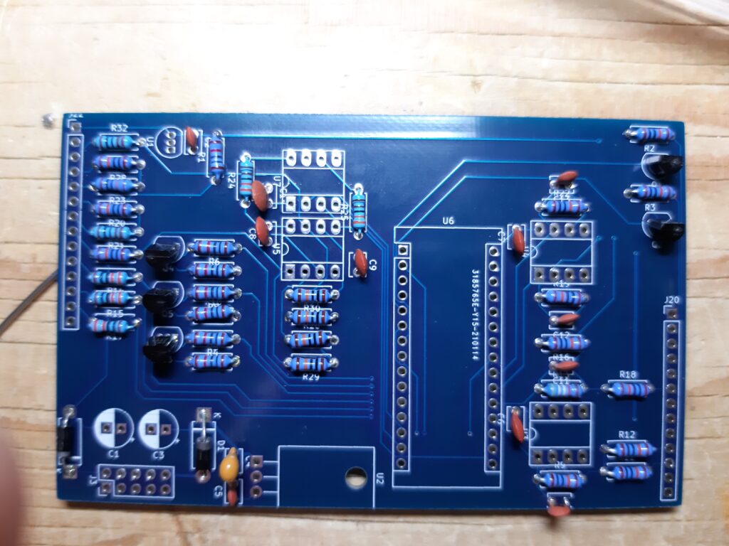
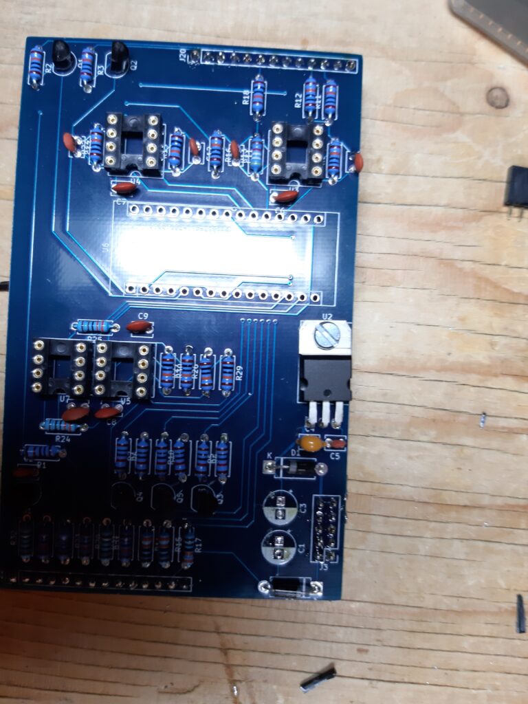
There is a control board and a main board. The main board goes on the back so I started with that one.
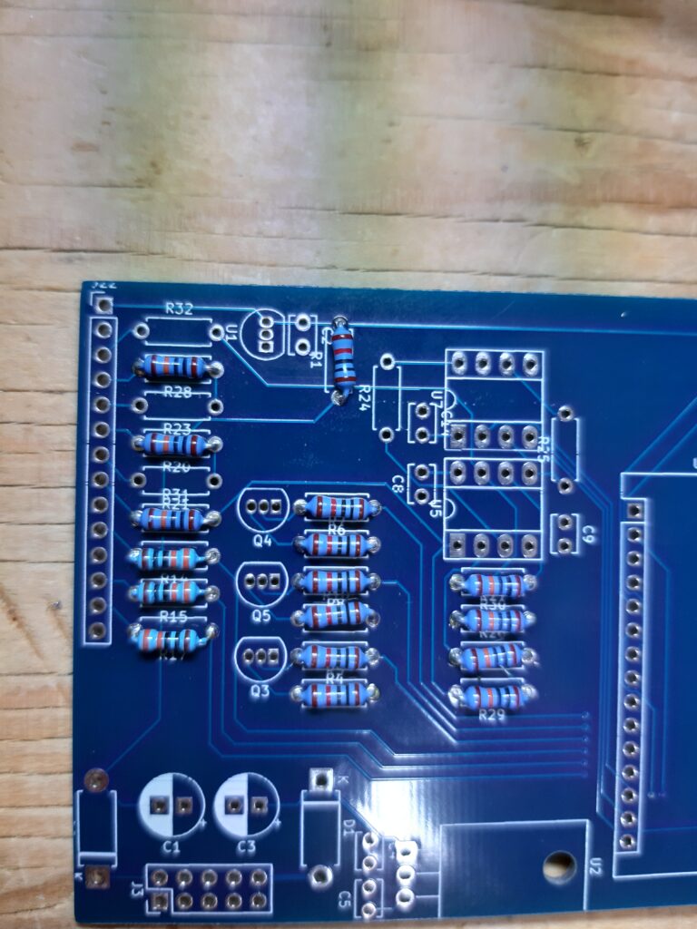
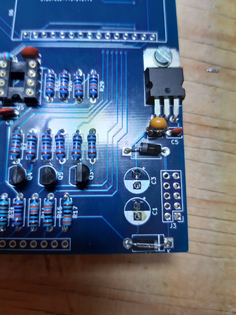
I started with the resistors. First the 10k ones, then the 100k and so on. There was a strange value resistor the 50k resistor. Didn’t have one but I had some 49.9k. Also a strange value 49.9k don’t remember the build that needed those. In the BOM there where two resistors valued at 1000 and 3300 so I assumed these where 1k and 3.3k
Next placing the diode’s and caps.
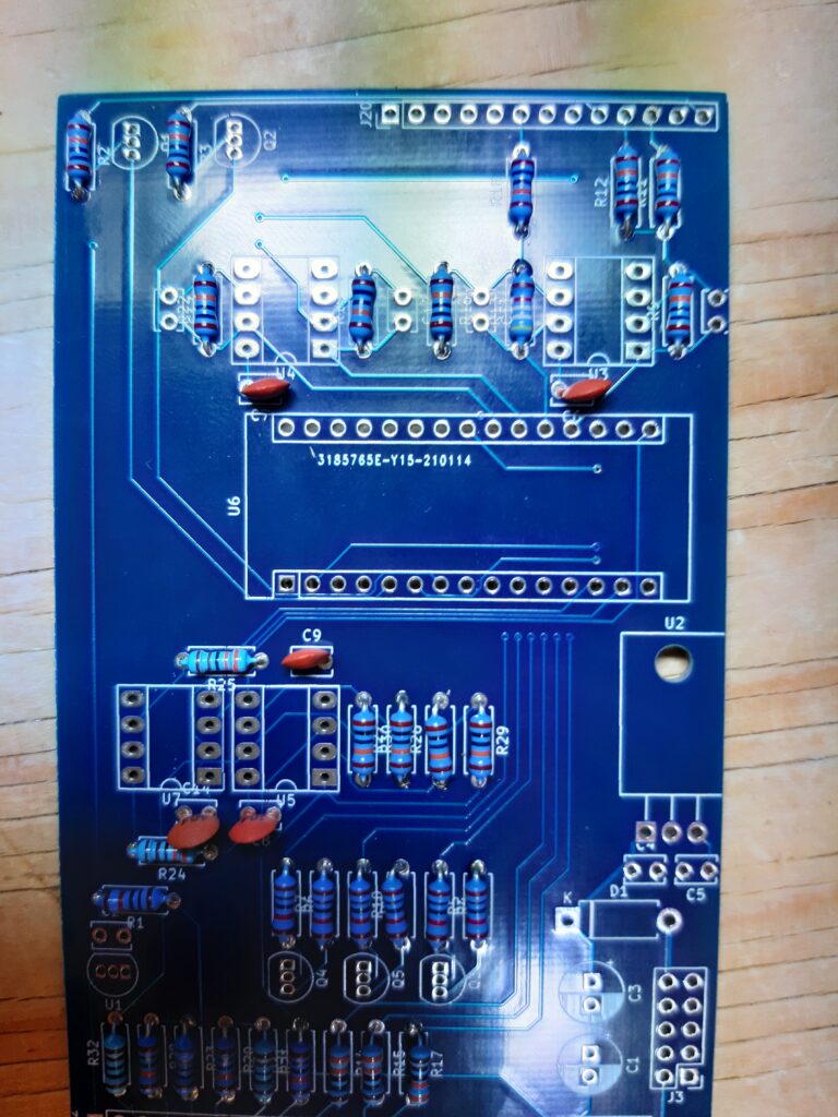
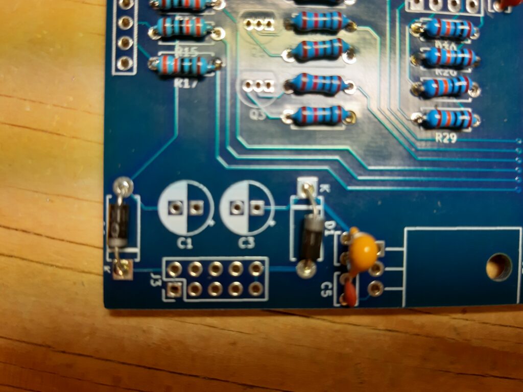
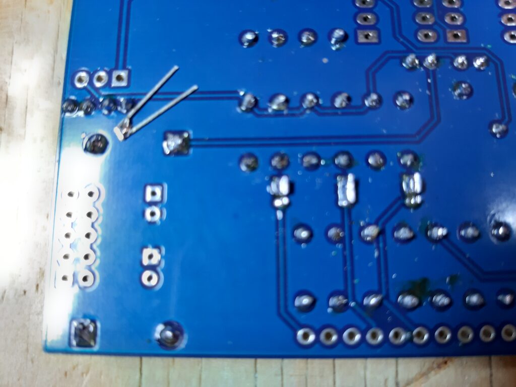
Then the transistors. Migueldetool used the normal footprint for these. I hate this footprint cause my eyes aren’t as good as they use to be and I end up soldering bridges between them. But nothing real my solder sucking tool can’t fix.
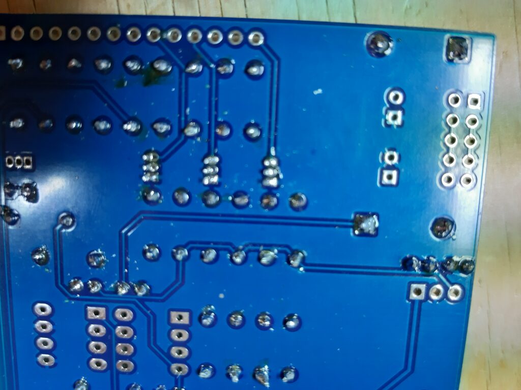
then the rest of the parts, sockets, and so on, until the power connector and big caps where to be soldered. I thought it would be smart to ignore the silkscreen and put them on the back of the board.
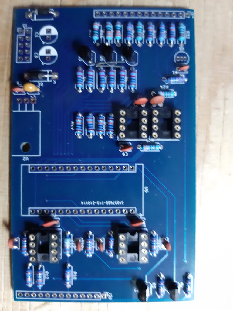
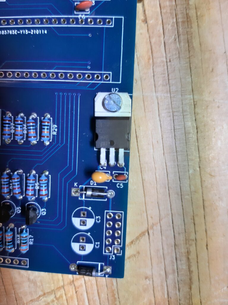
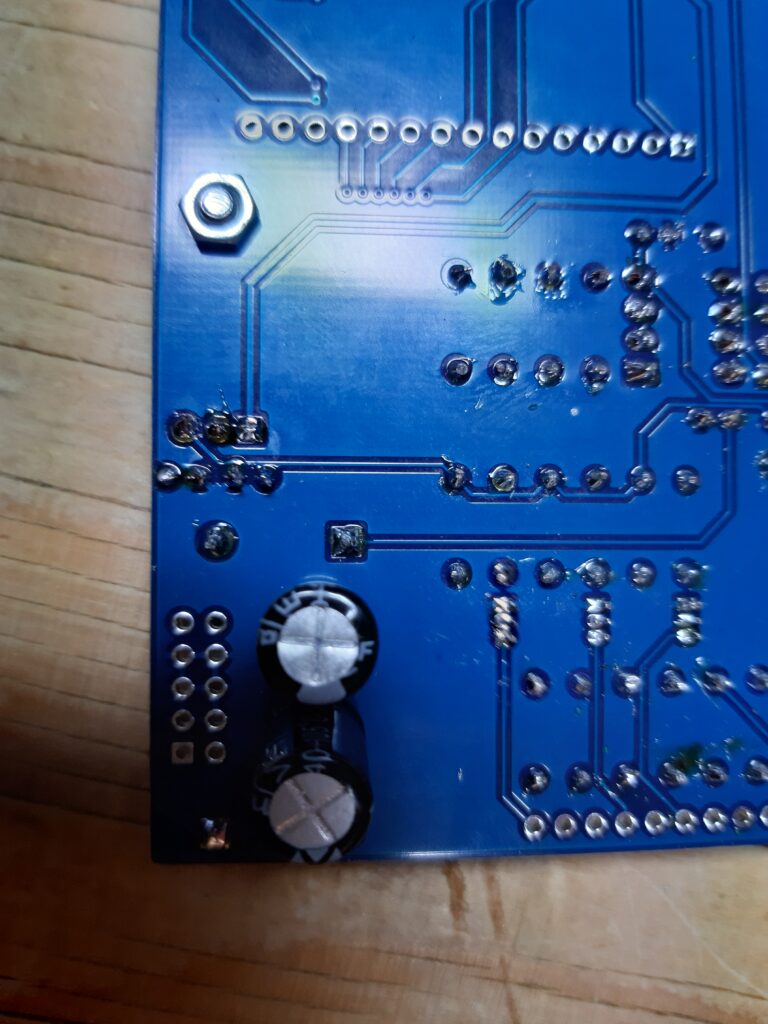
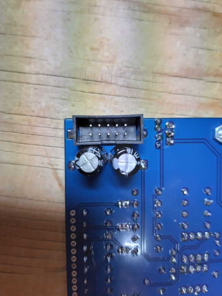
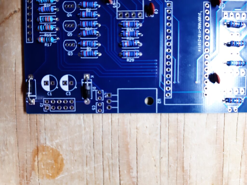
But when placing the headers i found myself in trouble. The components are facing the backside. Where I normally sandwich them this was not the case here. So now the power header would not fit and the capacitors where to big. My bad, so these have to be replaced.
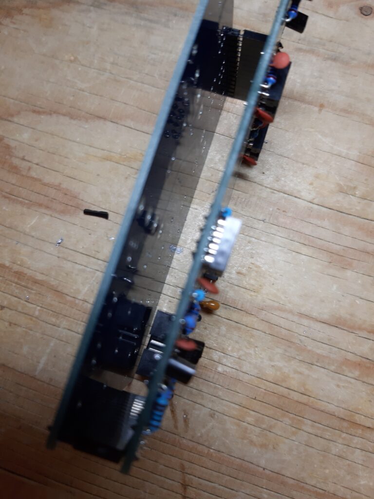
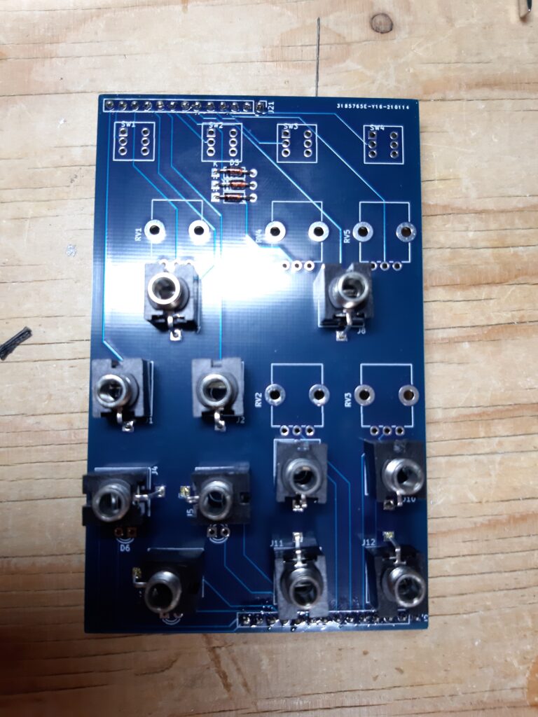
After soldering the power header and big capacitors on the right side (as the silkscreen told me) the back board was finished. Time to start with the front/control board.
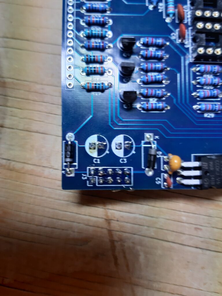
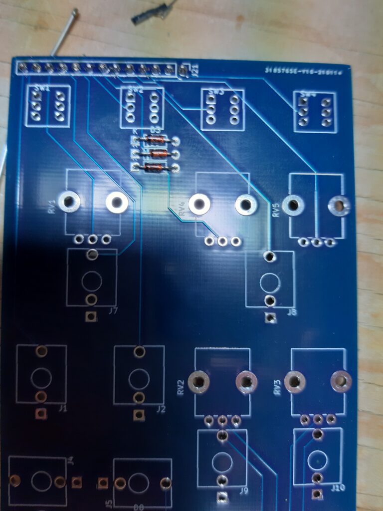
There are 3 diodes to be soldered on the front board. I placed these (and later found out Migueldetool told me the silkscreen for these is wrong. Hmm maybe I should read instructions before soldering.
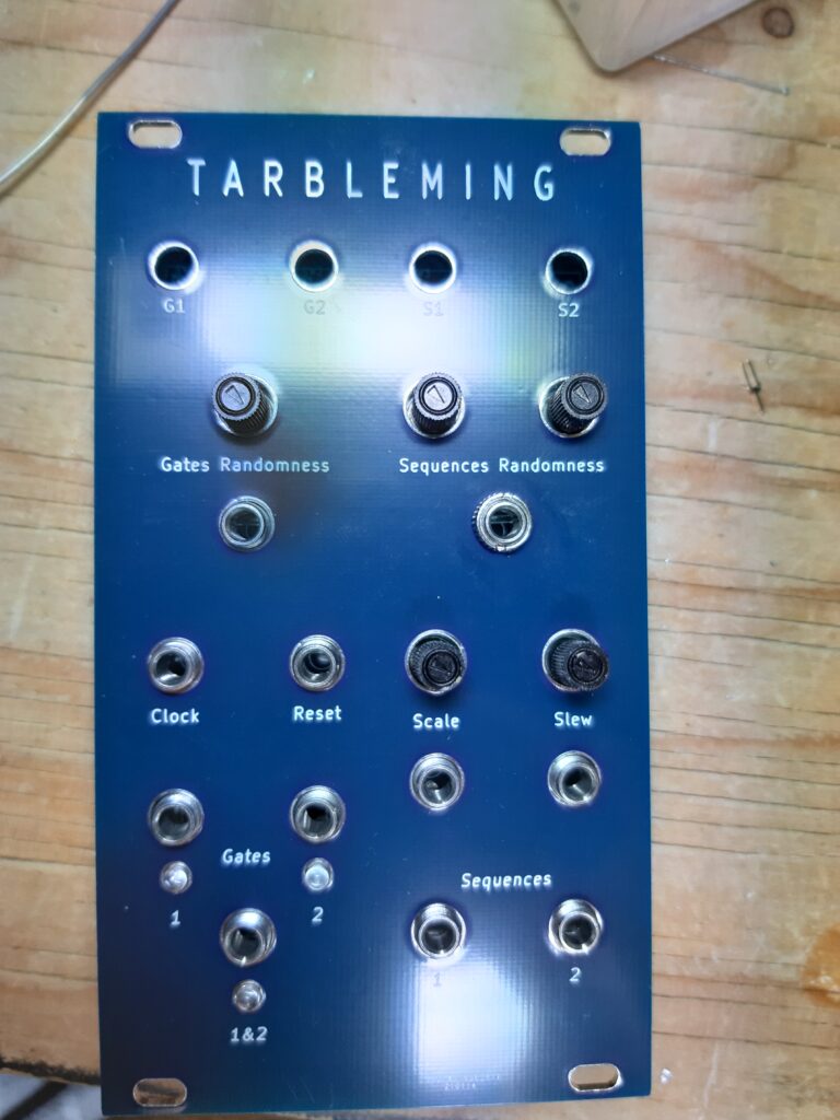
After the diodes I put the jacks on, then the potentiometers and the leds. The buttons I placed last and then found out the panel doesn’t fit with the button caps on. Will leave them off for now,
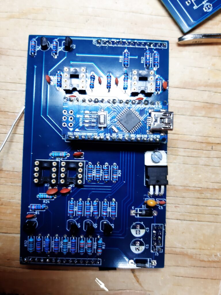
So let program a arduino nano with the code Migueldetool send me. There where a few errors in the code. First I needed a library installed. Nowadays this is easy. Then there where a few compiling issues with variable/arrays in a loop missing the counter “[i]”. After this the code compiled and I was able to upload to the arduino.
Next was doing some measurements and installing the chips and arduino nano on the pcb. And then powering it up.. and…. nothing….
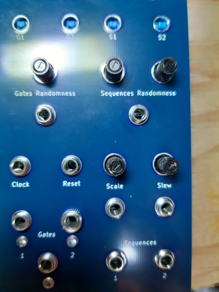
Oke..Well it says gates, it has leds, it mentions sequences and something called clock. Well I didn’t see any code for a internal clock, does it need a clock ?
There we go some flashing leds. It works bit those leds flash fast, let’s speed down the clock. If it had a screen it would go blue. Reset the nano and it started flashing again and a bit slower this time with the clock adjusted.
I haven’t had the time to read the code to understand is but if I have to guess. This module put outs random sequences of voltages and gates. A bit like the turing machine. It has two gates and sequences output and third gates out when gate 1 and 2 are both on.
I like this module just from seeing it’s potential. Hopefully I have a bit of time to read to code and started testing it some more. I still need the diodes on the front to be de-soldered and placed correctly. Do some measurements as instructed by Migueldetool. Maybe even de-solder a resistor or two.
So probably more to come on this module. I hope Migueldetool keeps working on it cause I think it has some great potential.