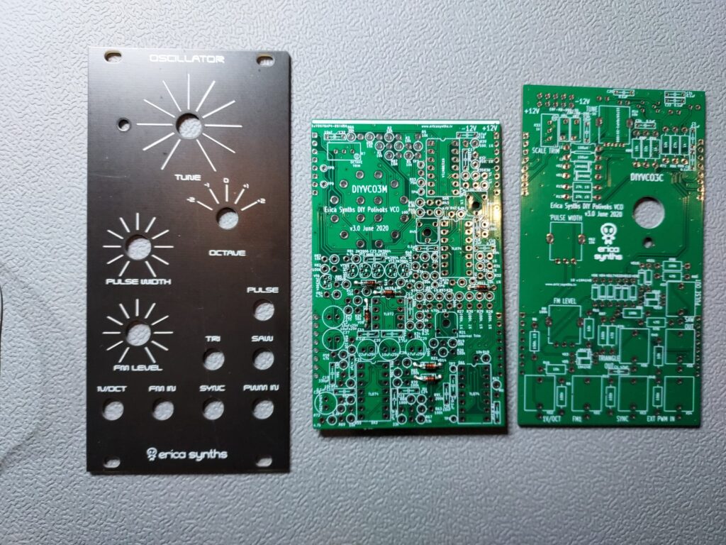
I have a love and hate relation with Erica Synths DIY modules. Some are quite nice to build but most of them are just terrible to build. I makes me wonder why Erica has left the DIY scene. I’m glad the put the designs on GitHub for the modules that they call legacy DIY. But I think the support desk was just overloaded cause these modules are just a pain in the butt to solder and are prone to make mistakes on. I had the VCO in my drawers for awhile and it was time to build it.
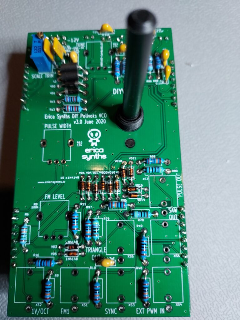
I got the pcb and panel from a trade, so I can only build one. The resistors on this pcb are standing up. That is one of the first thinks I don’t like on these Erica Synth designs. There are test points on the pcb but make sure not to put one of the resistor leg in one of those, cause there pretty close to each other. I’ve seen a few post on the internet where people have made this mistake. It’s a big build that will take a few hours and while doing the first part of the build. I already found out I don’t have all the parts.
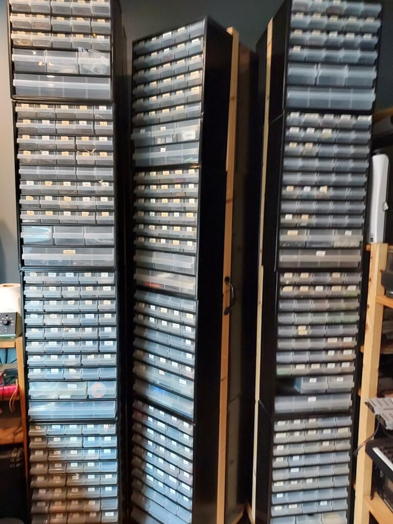
Then again whom has 6.19k resistors in stock? Strangely I don’t while one of these cabinets is full of resistors on both sides.
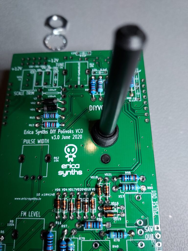
I started off by putting all the diodes on the main board. I tend to work from low to high. Diodes first, then resistors and then the sockets, etc. But with this pcb I did the resistor after the socket cause following the rule from low to high with standing resistors being higher then the sockets for the chips.
There is much special going on with the first part of this build just a lot of resistors and some strange values (6.19k, 910 ohm)
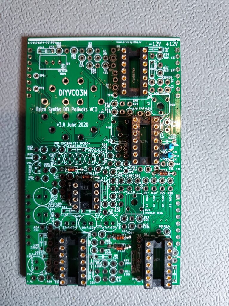
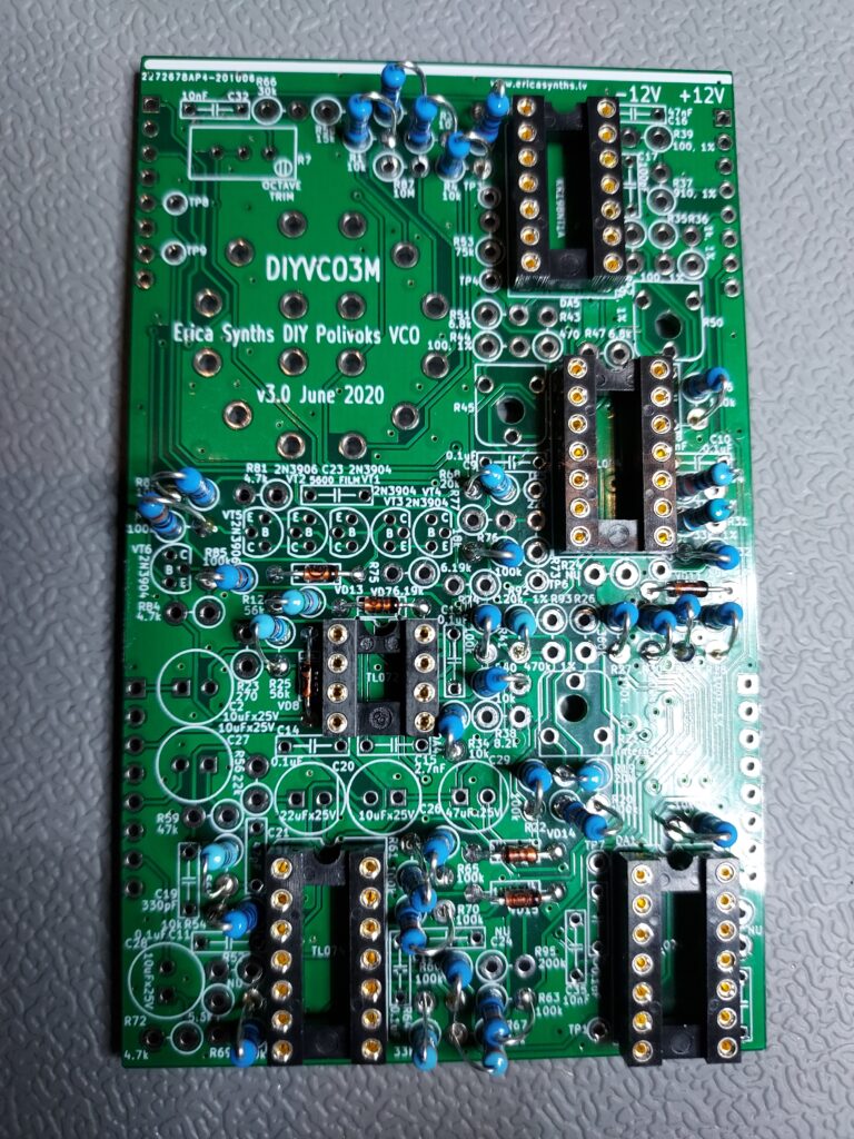
Just keep soldering resistors until you got them all in place.
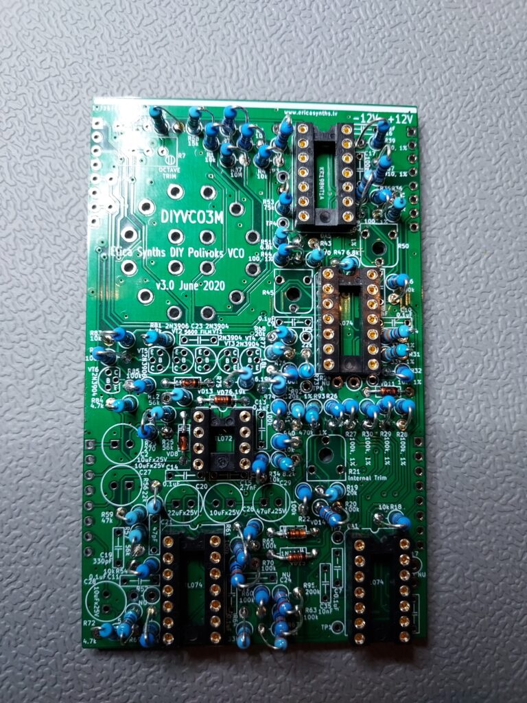
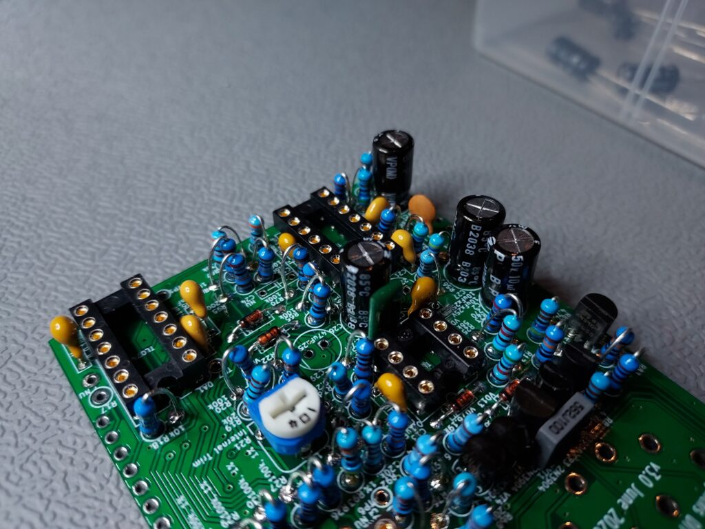
Then start with the capacitors and other remaining parts.
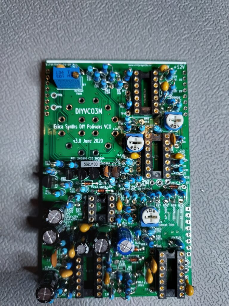
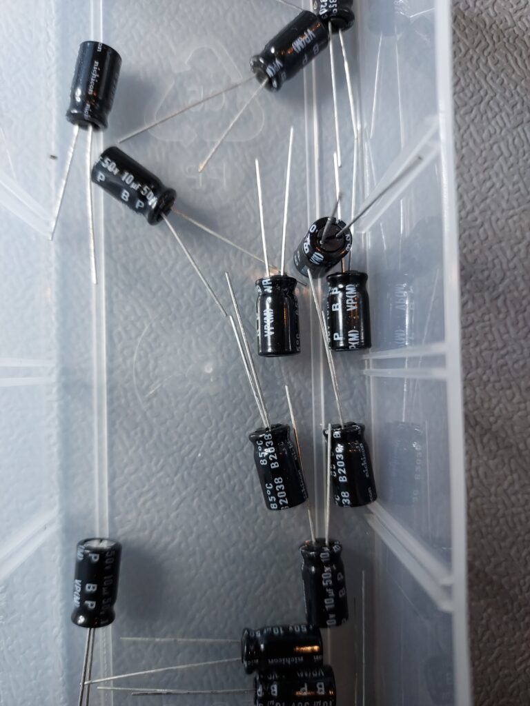
Have a look out for the 10uf capacitors these are non polarized (there is no line for minus on them)
Then do not make the mistake I did. It was late and I needed to stop building but I didn’t and placed the encoder on the wrong side of the board.
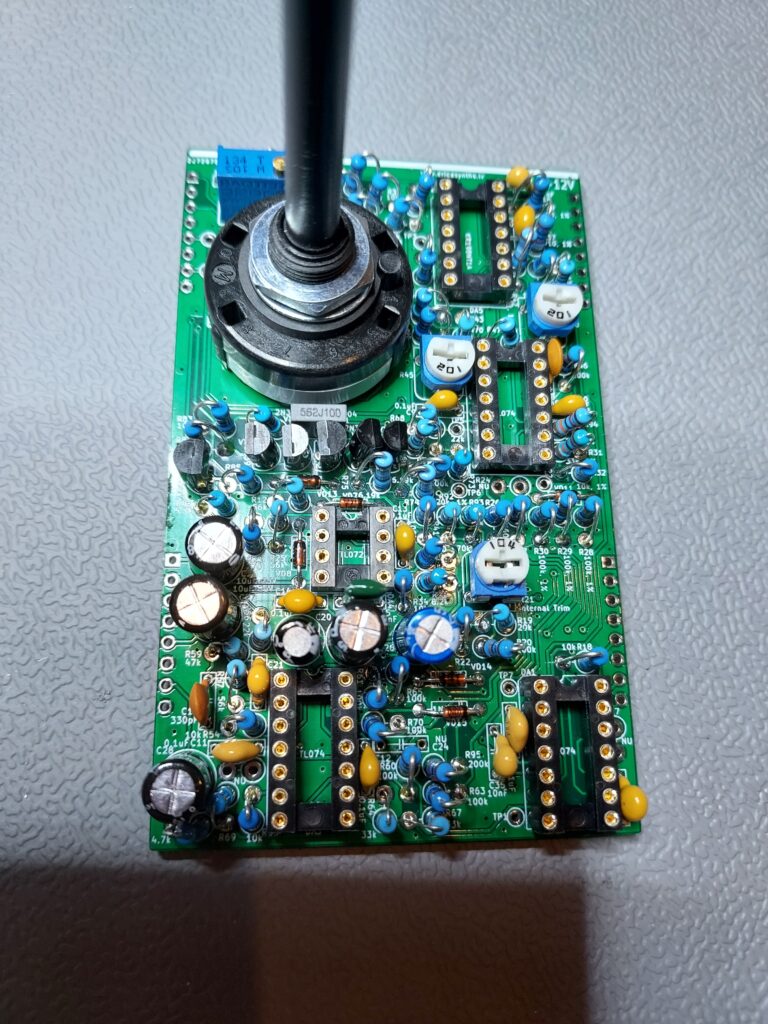
don’t do this
I was lucky and didn’t solder al the pins of the encoder before I found out my mistake. And was able to desolder it quite easy. Also notice the notch/ round pin on top of the encoder. This needs to fit on thru the other pcb.
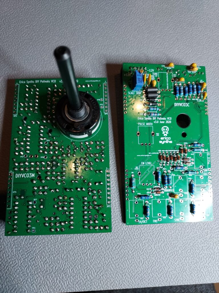
Here you can see how the board line up with the round pin on top of the encoder
Both board are nearly finished. Notice the reseting fuses. They are a bit on the high side for the panel to fit nicely. But I was able to bend them a bit
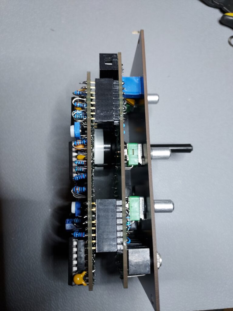
The encoder is quite high so the boards would not fit with normal headers. I used headers with extra long pins and just cut the pins off making them float a bit from the pcb.
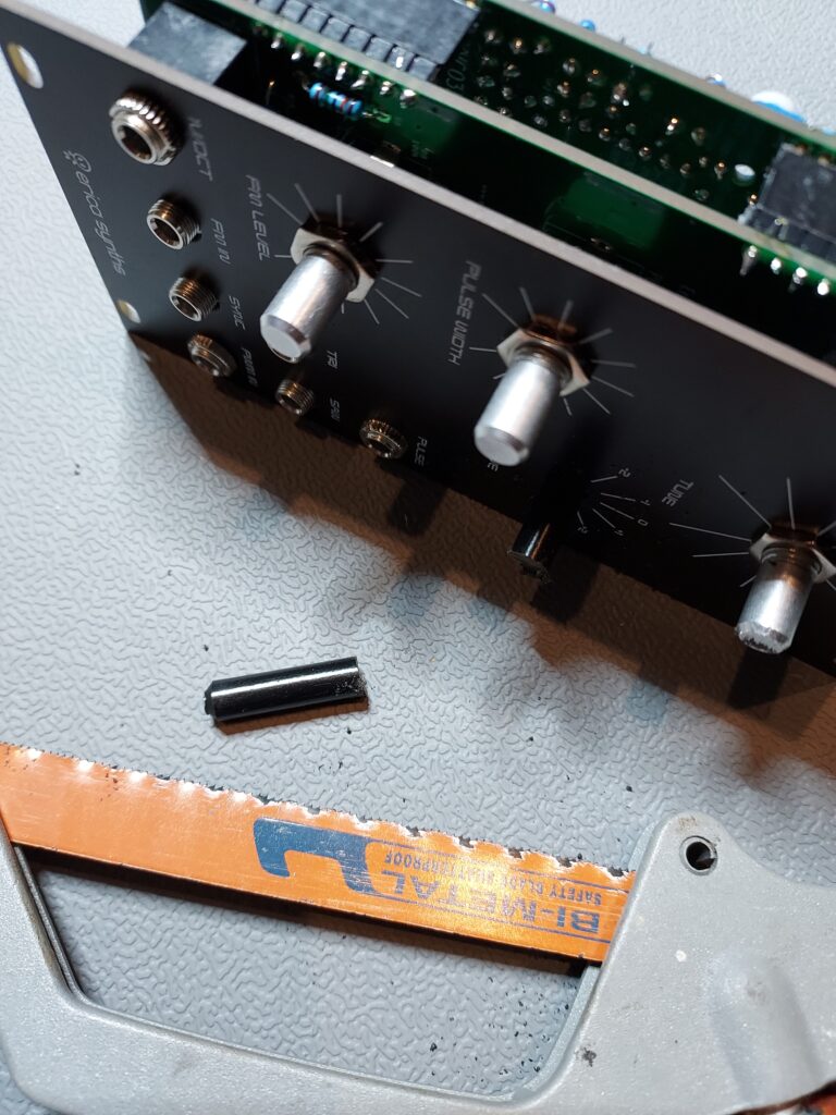
The encoder is quite long this was easy fixed with a iron saw.
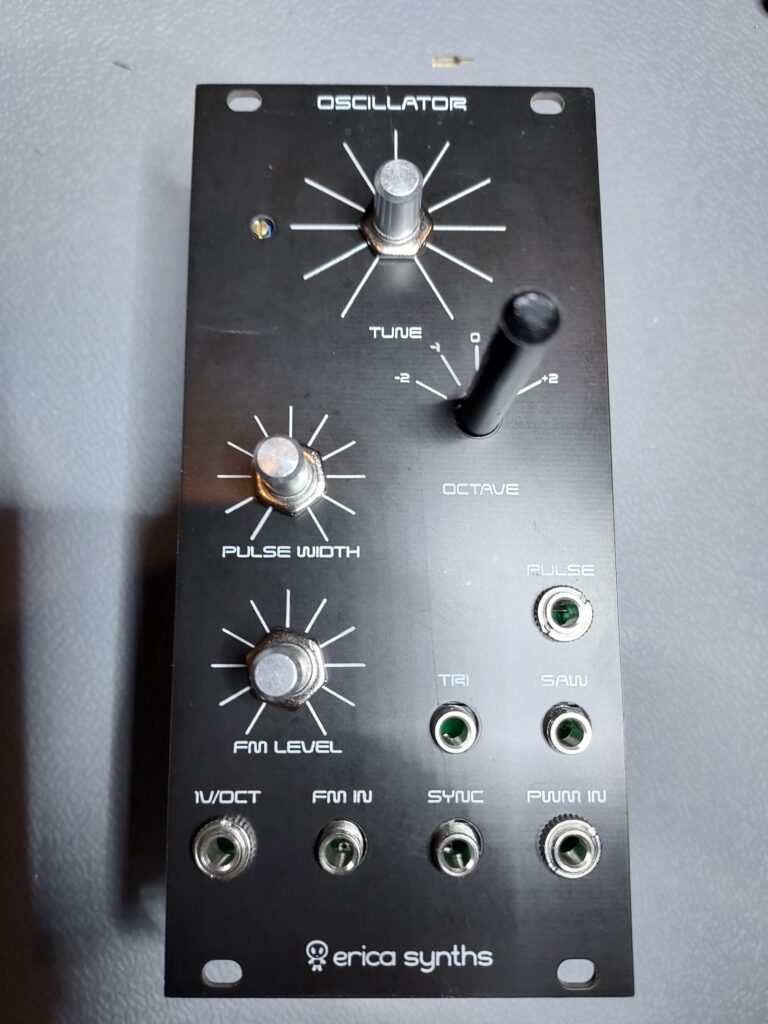
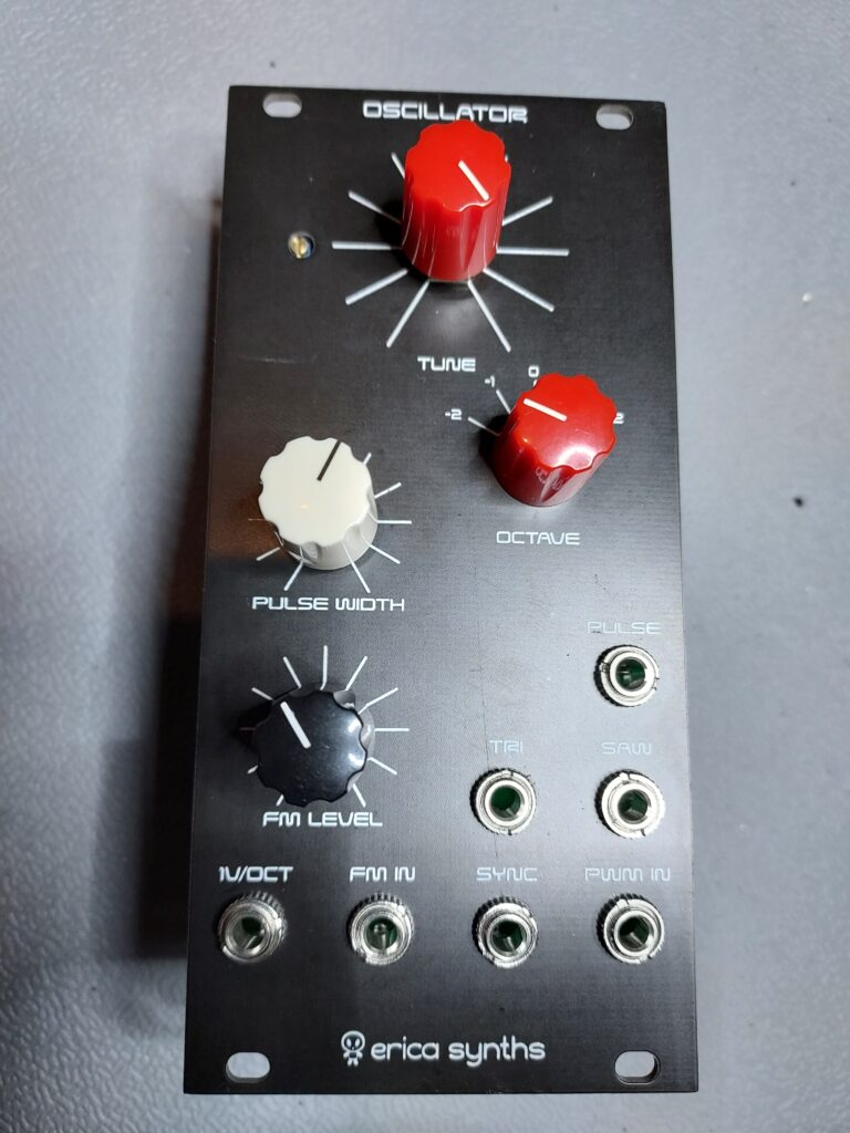
In the end the knob where added and the module is finished
I to be fair. It was again not the easiest to build, prone to make mistakes, headers that do not fit without extra long pins… But the darm thing sounds great!!!
Did you get this one tuned?
I don’t know for sure anymore. It’s been awhile since I build it. It defiantly needs a re-tune.