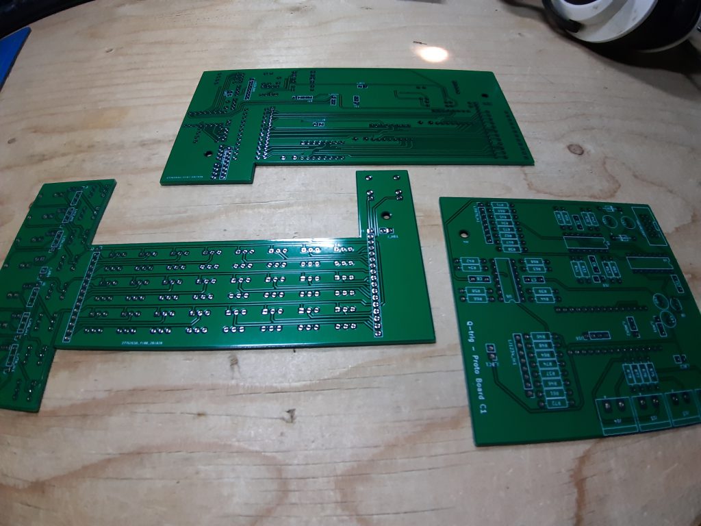
Well this week the Dotty prototype boards where in the mailbox. I was quite happy to see the boards, at first glance it all look fine. But will the boards fit together, did I make any mistakes. Let’s start soldering.
I began soldering the boards that evening. Starting out with the diode’s and then the resistors. Here I ran into my first problem. I made the schematics but I didn’t put in any resistor values. So the BOM just told me to place a resistor not what value it should be. And with only numbers on the board I needed to update the schematics.
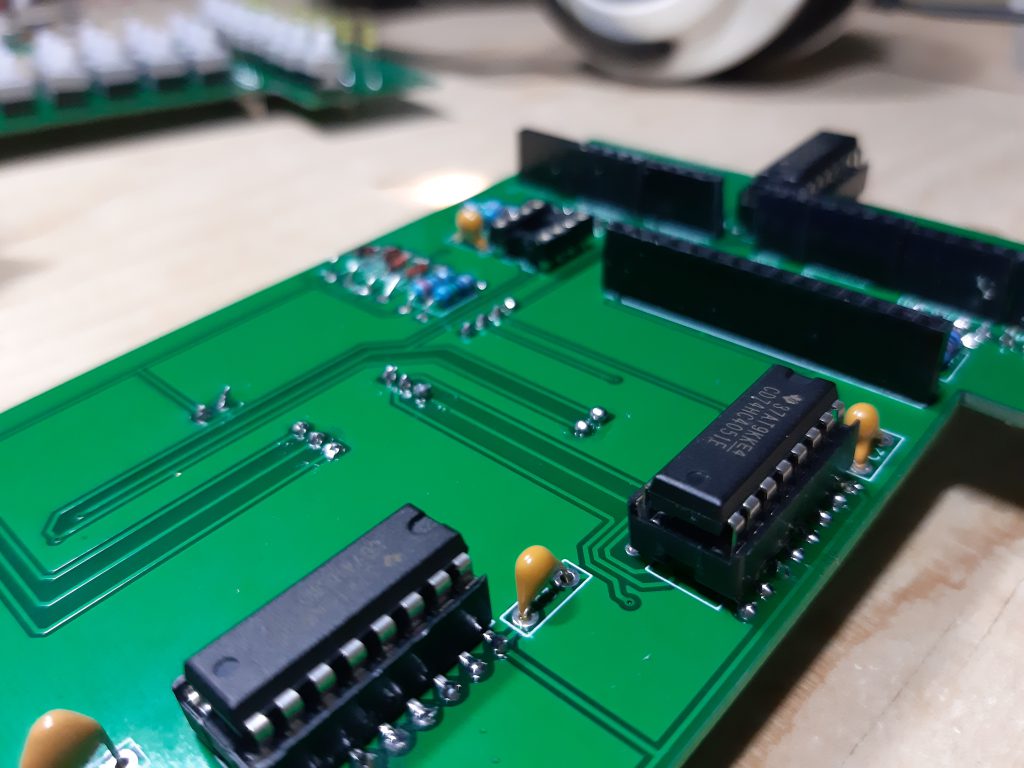
Well look what we got there. Found a few resistors in the schematics that I think are not really needed. Why did I put those there.. added to the ToDo list. When copy pasting and editing a schematic’s some error can slip in. One of the reasons Dotty is prototype right now. With the updated schematics I could export the BOM. Place all the resistors and then it was time for bed.
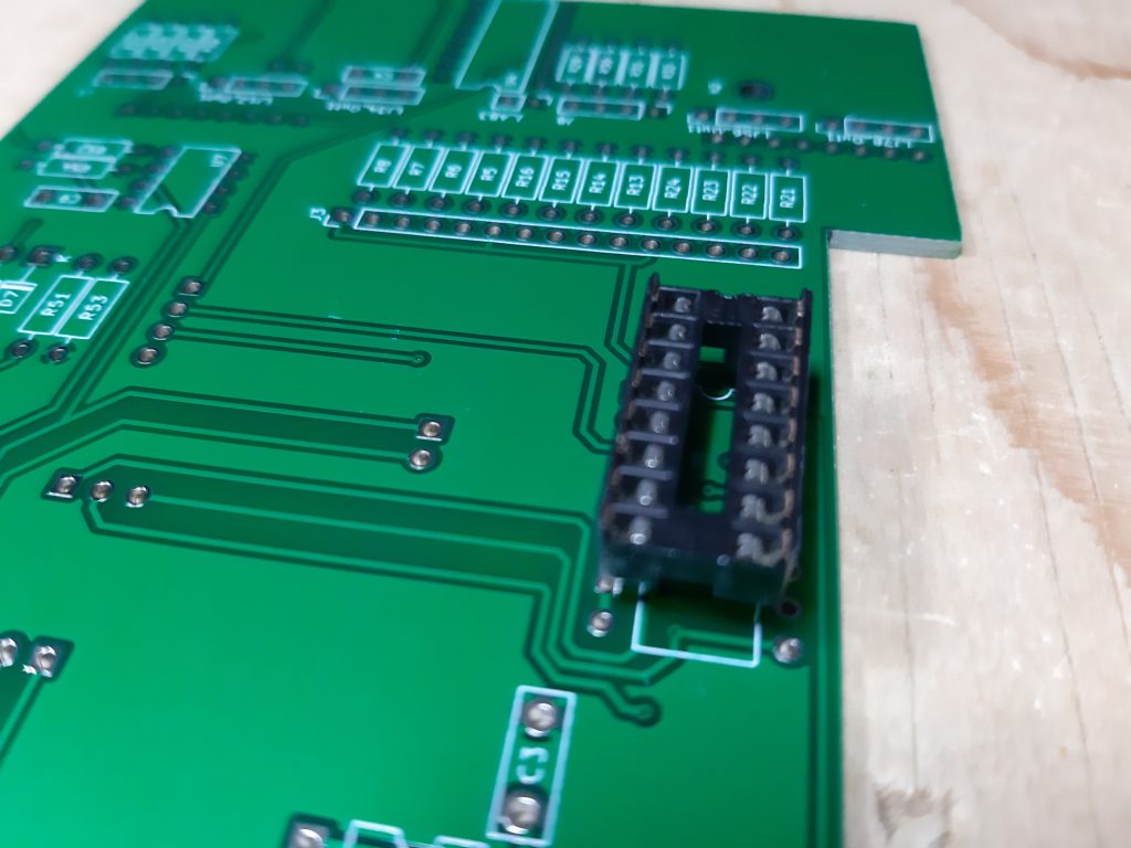
Next day I wanted to place the sockets for the chips. Here I ran into the second error. On the 4051 chip I used the wrong footprint. Meaning the socket didn’t fit, it was to wide. With a bit of bending and creative soldering I did get the sockets in place
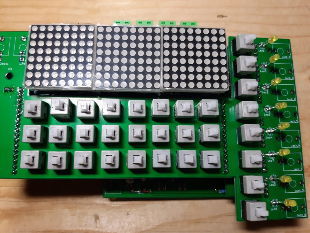
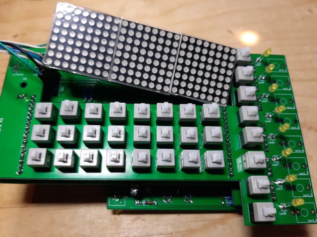
Next up the headers. The big question, do the headers line up and will the boards fit. The headers fit, but perhaps some repositioning is in place cause they weren’t easy to fit. With the headers in place, the boards where fit together and it looks…uhm big.
Last up soldering the leds and buttons. And when I tried to fit the led matrix I found a third error. The header is mirrored. It will fit in the header but the 5 volt should be on the top pin not the bottom one. Nothing a few wires won’t solve.
Well let’s power it up.. and.. nothing…
Before placing the chips and arduino i did some measurements on the sockets. The TL074 didn’t get any power. Found the error in the decoupling capacitors. These where drawn not as decoupling caps in the schematic but inline. I took them of and just placed a wire bridge there. So the chip will get power but are decoupled.
Powering it up again and still now measurements on the sockets
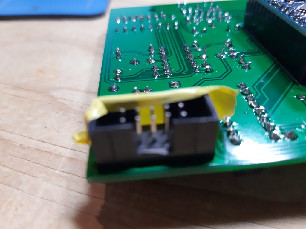
Error number five the power header should have been on the other side of the board. And I think i put the -12 volts and 12 volts wrong way round. The diode’s did stop the voltage going to the board so that’s is tested. A bit of cutting and I got myself a new shrouded header. Got the -12 volt on the right diode so let power it again.
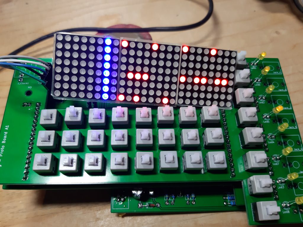
Now it powers up..
So I made a few mistakes, but that’s why you prototype. I do have a better prototype now then the three strip-boards. So I will first start on the code and we will see what changes the board need to fit my wishes.
- power header
- header led matrix
- footprint 4051
- Check schematics for not needed resistors
- decoupling tl074
and probably more when testing Dotty it a bit more….